
Operator's Manual


1
All Rights Reserved
Printed in the USA
2002 by The Toro Company
8111 Lyndale Avenue South
Bloomington, MN 55420-1196
Form No. 3326-168
Installation
Instructions
Model No. 04491
Rear Roller Brush
Greensmaster
3200 Series with Groomer
Note: Some components may have already been assembled
loosely at the factory. Some components may have to be
loosened or removed before installation. The right-hand
brush drives are shown in all figures.
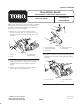
1. Remove the 2 screws and lock washers from the
groomer drive cover (Fig. 1). Also remove the screw
with the grease fitting or relief valve, the washer, and
the spacer.
1
3
2
2
Figure 1
1. Drive cover
2. Screw
3. Screw with grease
fitting/relief valve
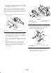
2. On the same end of the cutting unit, remove the locknut
and flat washer from the carriage bolt securing the
height-of-cut bracket to the cutting unit side plate
(Fig. 2).
3. Remove grease fitting from end of roller shaft and
replace with 90 grease fitting (Fig. 2).
1
2
3
4
5
Figure 2
1. Height-of-cut bracket
2. Locknut and flat washer
3. Carriage bolt
4. Cutting unit side plate
5. Grease fitting
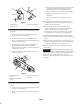
4. Thread a hex extension onto the carriage bolt (Fig. 3).
Tighten the hex extension securely against the cutting
side plate.
1
2
Figure 3
1. Long hex extension 2. Lower bedbar adjuster
bolt