
Operator's Manual


2
5. Repeat steps 2 and 4 on the opposite end of the cutting
unit using to mount the hex extension. Check and adjust
the height-of-cut as required.
Note: On cutting unit models 04470, 04471, 04480 and
04481 only, remove the lower bedbar adjuster bolts and
install new special bolts reversed as shown in Figure 3. The
bedbar may have to be removed to install the new special
bolt.
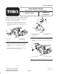
6. Remove the plastic belt cover from the brush kit drive
assembly (Fig. 4).
1
2
Figure 4
1. Belt cover 2. Drive assembly
7. Insert the lip of the drive assembly pivot plate into the
hole in the groomer drive cover. Secure the pivot plate
to the groomer drive cover with 2 special shoulder bolts
(Fig. 5). Tighten the bolts securely.
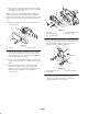
8. Loosely secure the pivot plate slotted bracket to the hex
extension with a hex head screw (M10) and flat washer
(Fig. 5).
9. Install the small drive pulley and square key to the
groomer drive shaft with the screw with the grease
fitting or relief valve (previously removed), the external
tooth lockwasher, and the flat washer. Tighten it
securely (Fig. 5).
1
2
3
4
5
Figure 5
1. Pivot plate
2. Special shoulder bolt
3. Hex head screw, M10
4. Pivot plate slotted bracket
5. Small drive pulley
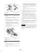
10. On the other end of the cutting unit, loosely secure the
bearing adjustment plate to the hex extension with a hex
head screw (M10) and flat washer (Fig. 6). Do not
overtighten; the brush must pivot freely.
1
2
3
Figure 6
1. Bearing adjustment plate
2. Hex extension
3. Hex head screw, M10
11. Secure the support bracket to the underside of the
cutting unit tab with 2 hex head screws (M6) and
locknuts. Tighten the screws (Fig. 7).