Form No. 3328–944 Dethatcher Kit Greensmaster 3000 Series Model No. 04493—Serial No.
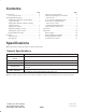
Contents Specifications . . . . . . . . . . . . . . . . . . . . . . . . . . . . . . . General Specifications . . . . . . . . . . . . . . . . . . . . . Adjusting Dethatching Unit . . . . . . . . . . . . . . . . . . . . Adjusting Reel Blades for Positive Setting (Above Ground) . . . . . . . . . . . . . . . . . . . . . . . . Adjusting Reel Blades For Negative Setting (Below Ground) . . . . . . . . . . . . . . . . . . . . . . . . . Adjusting Grass Shield . . . . . . . . . . . . . . . . . . . . .
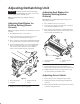
Adjusting Dethatching Unit Adjusting Reel Blades For Negative Setting (Below Ground) Important Read this Operator’s Manual thoroughly before operating the dethatching unit. Failure to do so may result in damage to the dethatching reel. Note: The dethatching unit is shipped completely assembled. Note: Maximum recommended negative setting is 1/4” deep blade penetration. Adjusting Reel Blades for Positive Setting (Above Ground) 1. Place dethatcher unit on a level surface. 2.
Note: As dethatcher blades wear, the diameter of the reel will decrease and setting will change. Check adjustment periodically to insure desired setting is achieved. 3. Tighten locknuts and jamnuts securing roller scraper to brackets. Adjusting Rear Wheel Scrapers 1 1. Loosen jam nut and locknut securing each rear wheel scraper to bracket. 2. Adjust each scraper until there is .030” – .060” clearance between front edge of scraper and wheel. 2 2 1 Figure 3 1. Grass shield 2.
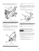
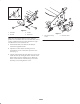
3 2 2 1 4 1 Figure 6 1. Pull frame 2. Lift roller 3. Lift arm 4. Pull link kit Figure 7 1. Reel drive mounting screws Note: When mounting Dethatcher Unit in right front position on Greensmaster 32xx series traction units, remove counter weight from left end of unit and mount on right end. Motor to be connected to left end. 1. Install Pull Link Kit, Toro Part No. 94–9630 per instructions supplied with kit. 2. Adjust the reel drive motor mounting screws so approximately 1/2 in.
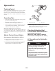
Operation 2 Training Period Before operating the dethatching units on a green, evaluate the performance of the dethatcher at the desired setting. Operate in a clear, unused area to determine if the desired results will be achieved. Adjust the dethatcher if a change is desired. Operating Tips 1 • Operate the traction unit at full throttle varying ground speed to meet dethatching loads. Figure 8 • Maximum recommended negative setting on the dethatcher blades is 1/4” deep penetration. 1.
B. Procedure for Manifold Relief Valve Pressure Check: Caution Operate all hydraulic controls to relieve system pressure and avoid injury from pressurized hydraulic oil. Controls must be operated with the ignition switch in RUN and the engine OFF. Return ignition switch to OFF when pressure has been relieved. Remove key from the ignition switch. 1. Make sure hydraulic oil is at normal operating temperature by operating the machine for approximately 10 minutes. 2.
Optional Blade Configurations 1. On rear side of manifold, remove cap from the relief valve with an allen wrench (Fig. 9). The dethatching unit is shipped from the factory with 1/2” spacing between blades. Using different combinations of 1/4” thick spacers (Toro Part No. 17–1600) and 3/4” thick spacers (Toro Part No. 82–6600) blade spacings of 1/2”, 3/4”, 1” or 1–1/4” can be attained. 2 3 1 Figure 9 1. Manifold 2. Relief cartridge 3.
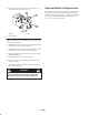
Lubrication There are (6) grease fittings on each dethatching unit, which must be lubricated after every 15 hours of operation. Lubricate using a #2 multipurpose lithium base grease. A hand operated grease gun is recommended for best results. 1. Wipe each grease fitting with a clean rag. 2. Apply grease to reel bearings, front roller bearings and rear wheel bearings until pressure is felt. (2) (2) (2) Figure 10 Important Do not apply too much pressure or grease seals will be permanently damaged. 3.
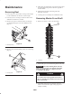
Maintenance 5. With a drive pin and hammer, loosen the locking collars by driving the locking collar in direction opposite to normal rotation. Removing Reel 6. Slide bearing housings and locking collars off dethatcher reel shaft. 1. Loosen (2) screws and washers securing counterweight to end of dethatcher unit. Remove counterweight. 7. Carefully pull reel assembly out of dethatcher frame. 2. Loosen (2) screws securing reel motor to other end of dethatcher unit. Remove reel motor.
Important The two 3/4” spacers must be assembled on each end of shaft. Do not invert individual dethatching reel blades. The order of disassembly is extremely important. Do not invert dethatching reel blades when disassembling or reverse the order when assembling. Note the thatcher blades index hole. The index hole is provided for assembly in order to obtain the PROPER HELIX FOR THE DETHATCHING REEL.