
Operator's Manual
1
All Rights Reserved
Printed in the USA
2002 by The Toro Company
8111 Lyndale Avenue South
Bloomington, MN 55420-1196
Spiker Kit
Greensmaster
3000 Series Attachment
Model No. 04494—Serial No. 220000001 and Up
Form No. 3329–232 Rev A
Operator’s Manual
Important Read this Operator’s Manual thoroughly
before operating the Spiker Kit. Failure to do so may result
in damage to the spiker.
Setup Instructions
Mounting the Pull Arm Bumpers
(Greensmaster 3050, 3100, 3150, and
3200)
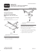
1. Using the dimensions shown in Figure 1, locate, mark,
and drill two 0.221 in. diameter holes in the underside
of each pull frame cross tube.
Note: Holes may already be present in the cross tubes.
1
19.43 in.
3.54 in. 0.75 in.
Figure 1
Greensmaster 3050, 3100, and 3150 Shown
1. Pull frame cross tube
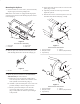
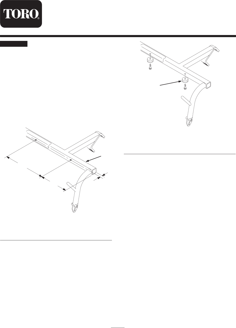
2. Mount the 2 recessed bumpers to the underside of each
pull frame cross tube with 2 washer head self tapping
screws (1/4 x 3/4 in.) (Fig. 2).
1
Figure 2
Greensmaster 3050, 3100, and 3150 Shown
1. Recessed bumper
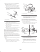
Adjusting the Rear Roller Scrapers
Note: The rear roller scraper is adjusted at the factory but
can be adjusted to meet turf conditions.
1. Loosen the locknuts securing the scraper to the frame.
2. Adjust the scraper until there is 0.03–0.06 in. clearance
between the edge of the scraper and the roller.
3. Tighten the locknuts securing the scraper.