%' ' $(# () '+ '" ( ! %#& $*
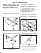
SET-UP INSTRUCTIONS IMPORTANT: Read this Operator's Manual thoroughly before operating the Spiker kit. Failure to do so may result in damage to the spiker. MOUNT PULL ARM BUMPERS (FIg. 1-2) 1. -#(! #' (-#)(- -")1( #( #!/, &) . ' ,% ( ,#&& # ")& - #( /( ,-# ) " */&& , ' ,)-- ./ Note: )& - ' 3 &, 3 *, - (. #( ,)-- ./ - 2. )/(. , -- /'* ,- .) /( ,-# ) " */&& , ' ,)-- ./ 1#." 2 &! 1 -" , " - & .
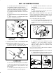
B. Assemble a jam nut and ball joint receiver onto each pull link assembly as shown in figure 5. C. Mount a pull link assembly to each end of carrier frame with spacer, washer and capscrew (Fig. 5). Make sure nylon bushing is in pull link. D. Install ball stud and lockwasher to each end of spiker (Fig. 5). E. Adjust pull links all the way forward and tighten jam nut. F. Slide sleeve back on each ball joint receiver and hook onto ball studs (Fig. 5). D.
27)68 740-2) 7,%*8 3* 6))0 13836 -283 7836%+) 89&) 32 *6%1) -+ #7-2+ 6))0 13836 *0%2+) %7 8)140%8) %2( 437-8-32-2+ %7 7,3;2 -2 *-+96) 03'%8) 1%6/ %2( (6-00 % (-% ,30) 32 7'6-&)( 0-2) 37-8-32 74%')6 &)8;))2 6))0 13836 *0%2+) %2( *6%1) ;,-0) %0-+2-2+ ,30)7 !)'96) 6))0 13836 %2( 74%')6 83 *6%1) ;-8, % 7)0* 8%44-2+ 7'6); 3928 '3928)6 ;)-+,8 83 6-+,8 7-() 3* 6)%6 74-/)6 ;-8, '%47'6);7 %2( ;%7,)67 ",) 6))271%78)6 "6%'8-32 #2-87 '3140