Form No. 3354-682 Rev A Dethatching Reel for Greensmaster® 3000 Series Model No. 04496—Serial No. 260000001 and Up Register at www.Toro.com.
Contents Introduction Introduction................................................................. 2 Setup............................................................................ 3 1 Adjusting the Reel Blades for Positive Setting (Above Ground)............................................... 3 2 Adjusting the Reel Blades For Negative Setting (Below Ground).................................... 3 3 Adjusting the Grass Shield ................................. 4 4 Adjusting the Front Roller Scraper........
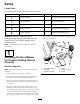
Setup Loose Parts Use the chart below to verify that all parts have been shipped. Procedure 1 3 4 5 6 Description Qty. Use No parts required – Adjust the reel blades for positive setting No parts required – Adjust the grass shield. No parts required – Adjust the front roller scraper. No parts required – Adjust the rear wheel scrapers. No parts required – Installing the dethatcher units. Important: Read this Operator’s Manual thoroughly before operating the dethatching unit.
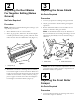
2 3 Adjusting the Reel Blades For Negative Setting (Below Ground) Adjusting the Grass Shield No Parts Required Procedure No Parts Required 1. Loosen (2) capscrews retaining front grass shield. 2. Adjust grass shield to desired setting and tighten capscrews. 3. Rotate dethatcher blades to insure blades do not contact or interfere with grass shield. Procedure Note: Maximum recommended negative setting is 1/4” deep blade penetration. 1. Place dethatcher unit on a level surface.
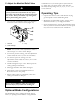
2. Adjust roller scraper until there is .030"-.060" clearance between scraper and roller. Figure 6 1. Rear wheel scraper 3. Tighten locknuts and jam nuts securing scrapers to brackets. Figure 5 1. Front roller scraper 2. Jam nut 2. Roller bracket Note: Scraper adjustment can be changed to meet turf conditions. 3. Tighten locknuts and jam nuts securing roller scraper to brackets.
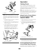
Operation Training Period Before operating the dethatching units on a green, evaluate the performance of the dethatcher at the desired setting. Operate in a clear, unused area to determine if the desired results will be achieved. Adjust the dethatcher if a change is desired. Note: When dethatching units are mounted on Greensmaster 3200, 3200–D or 3250–D Traction Units and are operated under heavy loads, an adjustment to the carrier frame and reel circuit relief valve may be required.
A. Precautions for Hydraulic Testing Engine speed can affect the accuracy of the tester readings. 4. The inlet and the outlet hoses must be properly connected and not reversed (tester with pressure and flow capabilities) to prevent damage to the hydraulic tester or components. Failure to use gauges with recommended pressure (psi) rating as listed in test procedures could result in damage to the gauge and possible personal injury from leaking hot oil. B.
C. Adjust the Manifold Relief Valve combinations of 1/4” thick spacers (Toro Part No. 17–1600) and 3/4” thick spacers (Toro Part No. 82–6600) blade spacings of 1/2”, 3/4”, 1” or 1–1/4” can be attained. Never adjust the relief valve with the hydraulic system pressurized. Hydraulic oil may spray out of the valve with the cap off. Personal injury may result. Always install the cap and tighten before pressurizing the system.
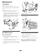
Maintenance Lubrication Service Interval: Every 20 hours There are (6) grease fittings on each dethatching unit. A hand operated grease gun is recommended for best results. Grease Type:#2 multipurpose lithium base grease. 1. Wipe each grease fitting with a clean rag. Figure 12 2. Apply grease to reel bearings, front roller bearings and rear wheel bearings until pressure is felt. 1. Bearing housing Important: Do not apply too much pressure or grease seals will be permanently damaged. 4.
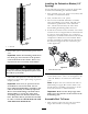
Installing the Dethatcher Blades (1/2” Spacing) Use the following procedure to assure the proper helix is attained when installing the dethatcher blades. 1. First, assemble one 3/4 in. spacer on reel shaft, then assemble a reel dethatcher blade. 2. Next, assemble the 1/2 in. spacer. 3. Do not invert individual dethatcher reel blades when reassembling on reel shaft. This will cause unsatisfactory performance of the dethatcher unit.
2. Slide a locking collar onto each end of reel shaft. Larger I.D. of collar to be facing outward. 3. Install and secure a reel bearing housing to each end of dethatcher unit with capscrews and lockwashers previously removed. 4. Position reel shaft assembly so it is centered between dethatcher side plates within .12". 5. Use a drive pin and hammer to tighten the locking collars on the reel shaft bearings. Tighten in direction of rotation. Tighten setscrews (2). 6.
The Toro General Commercial Products Warranty A Two-Year Limited Warranty Conditions and Products Covered The Toro Company and its affiliate, Toro Warranty Company, pursuant to an agreement between them, jointly warrant your Toro Commercial Product (“Product”) to be free from defects in materials or workmanship for two years or 1500 operational hours*, whichever occurs first.