
Installation Instructions

1
All Rights Reserved
Printed in the USA
W 2002 by The Toro Company
8111 Lyndale Avenue South
Bloomington, MN 55420-1196
Leak Detector Kit
Greensmaster
)
3200 Series
Model No. 04497
Form No. 3328–210 Rev A
Installation Instructions
Installing the Leak Detector
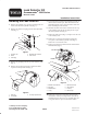
1. Remove the hydraulic cap, cap tether retaining bolt, and
washer from the main hydraulic tank (Fig. 1).
2. Remove the plastic insert plug from the main hydraulic
tank (Fig. 1).
1
2
5
4
3
Figure 1
1. Hydraulic cap
2. Tether
3. Insert plug
4. Breather and extension
5. Filler screen
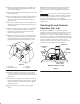
3. Remove the pipe plug from the top of the auxiliary tank
(Fig. 2)
4. Remove the breather and breather extension from the
top of the main hydraulic tank (Fig. 1).
1
3
2
Figure 2
1. Pipe plug
2. Cover plate
3. Auxiliary hydraulic tank
5. Top off the main hydraulic tank until fluid is visible at
the base of the breather port. This will ensure that the
maximum amount of air is purged from the main tank
before installing the leak detector.
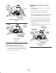
6. Install the breather and breather extension into the top
of the auxiliary tank and the pipe plug into the top of
the main hydraulic tank (Fig. 3).
7. Remove the filler screen (Fig. 1) and place it in the neck
of the auxiliary tank.
8. Remove the 5 capscrews and washers securing the
cover plate to the auxiliary hydraulic tank (Fig. 2).
Remove the cover from the tank.
9. Remove and discard 4 locknuts from the bottom of the
manifold block (Fig. 3).
1
8
4
6
7 6
2
5
3
Figure 3
1. Breather and extension
2. Pipe plug
3. Manifold block
4. O-ring
5. Main tank fill neck
6. Wire harness
7. R-clamp
8. Block fill cap
10. Remove the 4 protective insert plugs from the main
tank fill neck. Clean the mating surfaces of the block
and fill neck with a clean, dry rag. Carefully place the
o-ring from the loose parts over the fill neck boss.