
Installation Instructions

1
All Rights Reserved
Printed in the USA
2003 by The Toro Company
8111 Lyndale Avenue South
Bloomington, MN 55420-1196
Backlap/Reel Speed Kit
Greensmaster
3150/3200/3250-D
Model No. 04498
Form No. 3351–344 Rev. A
Installation Instructions
Accidental starting of the engine could seriously
injure you or other bystanders.
Remove the key from the ignition switch before
you do any maintenance.
Caution
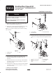
1. Remove the cartridge valve and seals from the right
side of the manifold assembly (Fig. 1).
2. Remove the cavity plug w/seals and the plug w/o-ring
from the top of the manifold assembly (Fig. 1).
Note: To ease removal of plugs, tap top surface of plugs
with a hammer.
1
2
3
Figure 1
1. Cartridge valve
2. Cavity plug
3. Plug
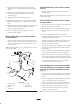
3. Install the logic cartridge to the right side of the
manifold assembly (Fig. 2). Torque to 35 ft.-lb.
(47 N⋅m).
4. Install the directional valve to the top of the manifold
assembly at the location shown in Figure 2. Torque to
35 ft.-lb. (47 N⋅m).
5. Install the flow control valve to the top of the manifold
assembly at the location shown in Figure 2. Torque to
35 ft.-lb. (47 N⋅m).
3
2
1
Figure 2
1. Logic cartridge
2. Directional valve
3. Flow control valve
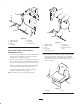
6. Install the detent kit components (Fig. 3) onto the flow
control valve using the instructions supplied with the
kit.
5
3
1
2
4
Figure 3
1. Detent kit—Flow control
valve
2. Detent kit—Directional
valve
3. Backlap bracket
4. Spacer plate
5. Switch