
Service Manual


Greensmaster 3320/3420 Hydraulic SystemPage 5 − 77
NOTE: The ports on the lift control manifold are marked
for easy identification of components. Example: S1 is
the solenoid valve and P is the supply port (see Hydrau-
lic Schematic to identify the function of the hydraulic
lines and cartridge valves at each port location).
CAUTION
Before continuing further, read and become fa-
miliar with General Precautions for Removing
and Installing Hydraulic System Components in
this section.
WARNING
If lift manifold is attached to machine, make sure
that cutting units are fully lowered before loos-
ening hydraulic lines or cartridge valves from lift
manifold. If cutting units are raised as compo-
nents are loosened in manifold, cutting units
may drop unexpectedly.
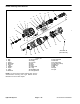
NOTE: The hydraulic manifold shown in Figure 52 uses
several zero leak plugs. These plugs have a tapered
sealing surface on the plug head that is designed to re-
sist vibration induced plug loosening. The zero leak
plugs also have an O−ring to provide a secondary seal.
If zero leak plug removal is necessary, lightly rap the
plug head using a punch and hammer before using an
allen wrench to remove the plug: the impact will allow
plug removal with less chance of damage to the socket
head of the plug. When installing plugs into the manifold,
torque plugs to the values identified in Figure 52.
For cartridge valve service procedures, see Control
Manifold Cartridge Valve Service in this section. Refer
to Figure 52 for lift manifold cartridge valve and plug
installation torque.
Hydraulic
System