
Service Manual


Greensmaster 3320/3420 Hydraulic SystemPage 5 − 19
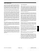
Right and Left Turn
The gear pump is directly coupled to the piston (traction)
pump. The gear pump supplies hydraulic flow for the
steering circuit (priority flow), for raising and lowering
the cutting units and for the traction charge circuit. The
gear pump takes its suction from the hydraulic reservoir.
Maximum circuit pressure of 1160 PSI (80 bar) is limited
by the relief valve located in the power steering valve.
With the steering wheel in the neutral position (not
turned) and the engine running, the power steering
valve spool is in the center position. Gear pump flow en-
ters the power steering valve at port (P) and goes
through the spool valve, by−passing the steering cylin-
der. Flow leaves the steering valve from port (E) to be
available for the raise/lower and traction charge circuits.
Right Turn
When a right turn is made with the engine running, the
turning of the steering wheel positions the power steer-
ing valve spool so that gear pump flow goes through the
top of the spool. Flow entering the power steering valve
at port (P) goes through the spool and is routed to two
places. First, most of the flow through the valve is by−
passed out port (E) and becomes available for the raise/
lower and traction charge circuits. Second, the
remainder of the flow is drawn through the steering
valve rotary meter and out steering valve port (R). Pres-
sure retracts the steering cylinder for a right turn. The
rotary meter ensures that the oil flow to the cylinder is
proportional to the amount of the turning on the steering
wheel. Fluid leaving the cylinder flows back through the
spool valve, out steering valve port (T) and then to the
traction charge circuit.
The power steering valve returns to the neutral position
when turning is complete.
Left Turn
When a left turn is made with the engine running, the
turning of the steering wheel positions the power steer-
ing valve spool so that gear pump flow goes through the
bottom of the spool. Flow entering the power steering
valve at port (P) goes through the spool and is routed to
two places. First, most of the flow through the valve is
by−passed out port (E) and becomes available for the
raise/lower and traction charge circuits. Second, the re-
mainder of the flow is drawn through the steering valve
rotary meter and out steering valve port (L). Pressure
extends the steering cylinder for a left turn. The rotary
meter ensures that the oil flow to the cylinder is propor-
tional to the amount of the turning on the steering wheel.
Fluid leaving the cylinder flows back through the spool
valve, out steering valve port (T) and then to the traction
charge circuit.
The power steering valve returns to the neutral position
when turning is complete.
Figure 11
v
P
TE
PORT BALL
LR
JOINT END
STEERING CYLINDER
1160
VALVE
PSI
POWER
STEERING
4.5
NEUTRAL POSITION
RIGHT TURN
LEFT TURN
NO CYLINDER
MOVEMENT
TO LIFT CONTROL
TO CHARGE
CIRCUIT
VALVE
FROM GEAR
PUMP
P
TE
PORT BALL
LR
JOINT END
STEERING CYLINDER
1160
VALVE
PSI
POWER
STEERING
4.5
TO LIFT CONTROL
TO CHARGE
CIRCUIT
VALVE
FROM GEAR
PUMP
PORT BALL
LR
JOINT END
STEERING CYLINDER
P
TE
1160
VALVE
PSI
POWER
STEERING
4.5
TO LIFT CONTROL
TO CHARGE
CIRCUIT
VALVE
FROM GEAR
PUMP
Hydraulic
System