Form No. 3436-581 Rev A Greensmaster® 3320 TriFlex® Traction Unit Model No. 04530—Serial No. 405600000 and Up Register at www.Toro.com.
This product complies with all relevant European directives; for details, please see the separate product specific Declaration of Conformity (DOC) sheet. Visit www.Toro.com for more information, including safety tips, training materials, accessory information, help finding a dealer, or to register your product.
Contents Electrical System Maintenance ........................... 37 Electrical System Safety ................................... 37 Servicing the Battery......................................... 37 Locating the Fuses ........................................... 38 Jump-Starting the Machine............................... 38 Drive System Maintenance .................................. 39 Checking the Tire Pressure............................... 39 Checking the Torque of the Wheel Nuts .......................
Safety This machine has been designed in accordance with EN ISO 5395 and ANSI B71.4-2017 and meets these standards when you complete the setup procedures. General Safety This product is capable of amputating hands and feet and of throwing objects. • Read and understand the contents of this Operator’s Manual before starting the engine. • Use your full attention while operating the machine. Do not engage in any activity that causes distractions; otherwise, injury or property damage may occur.
Safety and Instructional Decals Safety decals and instructions are easily visible to the operator and are located near any area of potential danger. Replace any decal that is damaged or missing. decal133-8062 133-8062 decal119-9346 119-9346 1. Press the pedal to unlock. decal115-8226 115-8226 1. Tipping hazard—read the Operator's Manual; wear a seatbelt; do not remove the roll bar. 5 2. Read the Operator's Manual for more information.
decal139-6493 139-6493 1. Lower and engage the reels. 8. Reel—mow 2. Raise and disengage the reels. 9. Reel—backlap 3. Mow direction 4. Fast 10. Choke 11. Engine—start 5. Slow 12. Engine—run 6. Neutral 13. Engine—stop 7.
decalbatterysymbols Battery Symbols Some or all of these symbols are on your battery. 1. Explosion hazard decal131-2046 131-2046 6. Keep bystanders away from the battery. 2. No fire, open flame, or smoking 7. Wear eye protection; explosive gases can cause blindness and other injuries. 3. Caustic liquid/chemical burn hazard 4. Wear eye protection. 8. Battery acid can cause blindness or severe burns. 9. Flush eyes immediately with water and get medical help fast. 5. Read the Operator's Manual. 1.
decal115-8156 115-8156 1. Reel height 3. 8–blade cutting unit 5. 14–blade cutting unit 7. Fast 2. 5–blade cutting unit 4. 11–blade cutting unit 6. Reel speed 8.
Setup Loose Parts Use the chart below to verify that all parts have been shipped. Procedure Description Use Qty. Roll bar Bolt (1/2 x 3-3/4 inches) Flange nut (1/2 inch) Seat Seat wire harness Steering wheel Locknut (1-1/2 inches) Washer Steering-wheel cap 1 4 4 1 1 1 1 1 1 4 No parts required – Activate and charge the battery. 5 Oil Cooler Kit—Greensmaster 3300 Series Traction Unit (Part No. 119-1691 [purchased separately]) – Install the optional oil cooler.
Description Use Qty. Declaration of Conformity Noise rating certificate 1 1 For CE compliance Ignition keys 2 Use a key to start the engine. 1 Installing the Roll Bar Parts needed for this procedure: 1 Roll bar 4 Bolt (1/2 x 3-3/4 inches) 4 Flange nut (1/2 inch) Procedure 1. Remove the top crate support from the crate. 2. Remove the roll bar from the crate. 3. Remove the 3 bolts that secure the right side cover to the machine and remove the side cover. 4.
move the seat, and connect it to the port on the bottom of the seat. 2 3 Installing the Seat Parts needed for this procedure: 1 Seat 1 Seat wire harness Installing the Steering Wheel Parts needed for this procedure: Procedure Note: Mount the seat in the front set of mounting holes to gain an additional 7.6 cm (3 inches) in the forward adjustment, or in the rear mounting holes for an additional 7.6 cm (3 inches) in the rearward adjustment. 1.
4 Activating and Charging the Battery No Parts Required Procedure g032705 Use only electrolyte (1.265 specific gravity) to fill the battery initially. Figure 7 1. Electrolyte WARNING 4. Battery terminals or metal tools could short against metal machine components, causing sparks. Sparks can cause the battery gasses to explode, resulting in personal injury. 5. • When removing or installing the battery, do not allow the battery terminals to touch any metal parts of the machine.
secure them with the bolts and nuts (Figure 8). Slide the rubber boot over the positive terminal to prevent a possible short from occurring. 6 WARNING Installing the Grass-Basket Hooks Incorrect battery cable routing could damage the tractor and cables, causing sparks. Sparks can cause the battery gasses to explode, resulting in personal injury. Parts needed for this procedure: • Always disconnect the negative (black) battery cable before disconnecting the positive (red) cable.
7 8 Installing the Cutting Units Setting the Clip-Control Feature Parts needed for this procedure: 1 Gauge bar 3 Cutting unit (obtain from your authorized Toro distributor) 3 Grass basket 3 Electric-reel-motor counterweight 6 Capscrew 3 O-ring No Parts Required Procedure The machine has a clip-control feature that varies the speed of the reels with the speed of the machine to maintain a constant clip. This achieves a consistent, high quality-of-cut and a uniform after-cut appearance.
10 Installing the CE Decals Parts needed for this procedure: 1 Warning decal (Part No. 136-8505) 1 CE mark decal 1 g271539 Figure 12 Production year decal 1. Production year decal Procedure 11 If you use this machine in a country that complies to CE standards, perform the following steps after you install the guard kit to the machine: • Apply the CE warning decal (Part No. 136-8505) Reducing the Tire Pressure over the existing warning decal (Part No. 136-8506).
Product Overview g014603 Figure 14 1. Traction pedal—forward 3. Steering-arm-locking pedal 2. Taction pedal—reverse g014674 Figure 13 1. Engine 5. Steering wheel 2. Roll bar 6. Traction pedal 3. Control panel 7. Footrest 4. Seat 8. Cutting units Controls g005105 Traction Pedal Figure 15 The traction pedal (Figure 14) has 3 functions: to make the machine move forward, to move it backward, and to stop the machine.
Throttle Lever Functional Control Lever The throttle lever (Figure 16) allows you to control the speed of the engine. Move the throttle lever toward the FAST position to increases the engine speed; move it toward the SLOW position to decrease the engine speed. The functional control lever (Figure 16) provides 2 traction selections plus a NEUTRAL position. You can shift from mow to transport or transport to mow (not to neutral) while the machine is in motion; no damage will result.
InfoCenter Control • ENGINE RPM/STATUS —indicates the engine rpm. • FAULT LOG—indicates that there is a current fault Using the InfoCenter LCD Display log to review. • GENERATOR VOLTAGE /STATUS —indicates the The InfoCenter LCD display shows information about your machine such as the generator status, the speed, and various diagnostics and other information about the machine and the battery pack. Figure 18 and Figure 19 illustrate the splash screen and main information screen of the InfoCenter.
DIAGNOSTICS SETTINGS ABOUT The DIAGNOSTICS menu lists various states that the machine currently has. You can use this to troubleshoot certain issues as it will quickly tell you which machine controls are on and which are off. The SETTINGS menu allows you to customize and modify configuration variables on the InfoCenter display. The ABOUT menu lists the model number, serial number, and software version of your machine.
2 0.150 3 0.200 4 0.250 5 0.300 6 0.375 7 0.475 8 0.600 9 0.750 10 0.925 not to use the clip-control feature, set the reel speed manually as follows: 1. Select the height-of-cut at which the cutting units are set. 2. Choose the desired ground speed best suited for conditions. 3. Using the appropriate graph (Figure 19) for 5-, 8-, 11-, or 14-blade cutting units, determine the proper reel speed setting.
Fuel-Shutoff Valve Faults menu that you or your distributor can use to identify the problem. Close the fuel-shutoff valve (Figure 22), behind the seat and under the fuel tank, when storing or transporting the machine on a truck or trailer. For a list of faults, refer to your Authorized Toro Distributor or the Service Manual. Seat-Adjusting Lever The seat-adjusting lever is located on the front, left corner of the seat (Figure 21), allowing you to adjust the seat forward and rearward.
Cutting Unit Power Disconnect Connectors Overall height Weight Before installing, removing, or working on the cutting units, disconnect the cutting units from the power supply by separating the cutting unit power disconnect connectors (Figure 23), located at the base of the rollover bar on the left side of the traction unit. Plug the connectors together before operating the machine. 205 cm (80.
Fuel Specification Operation Fuel tank capacity: 26.6 L (7 US gallons) Note: Determine the left and right sides of the machine from the normal operating position. Recommended Fuel: Unleaded gasoline with an octane rating of 87 or higher ((R+M)/2 rating method) Before Operation Ethanol: Gasoline with up to 10% ethanol (gasohol) or 15% MTBE (methyl tertiary butyl ether) by volume is acceptable. Ethanol and MTBE are not the same. Gasoline with 15% ethanol (E15) by volume is not approved for use.
Filling the Fuel Tank 1. During Operation Clean around the fuel-tank cap and remove it (Figure 24). During Operation Safety General Safety • The owner/operator can prevent and is responsible • • • g272992 Figure 24 • 1. Fuel-tank cap 2. • • Add the specified fuel to the fuel tank until the level is 25 mm (1 inch) below the bottom of the filler neck. This space in the tank allows the fuel to expand. Important: Do not fill the fuel tank • completely full. 3. 4. Install the cap.
• • Use extreme caution when operating the machine – Shut off the engine and remove the key. – Wait for all movement to stop. Operate the machine only in good visibility and appropriate weather conditions. Do not operate the machine when there is the risk of lightning. near drop-offs, ditches, embankments, water hazards, or other hazards. The machine could suddenly roll over if a wheel goes over the edge or the edge caves in. Establish a safety area between the machine and any hazard.
Checking the Machine after Checking the Safety-Interlock System Starting the Engine 1. Move the throttle lever to the FAST position. 2. Move the raise/lower mow control lever forward momentarily. Service Interval: Before each use or daily CAUTION If the safety interlock switches are disconnected or damaged the machine could operate unexpectedly, causing personal injury. • Do not tamper with the interlock switches.
2. 3. 4. Move the functional-control lever to the MOW position or the TRANSPORT position and try to start the engine. Driving the Machine without Mowing The engine should not turnover or start, which indicates that the interlock system is operating correctly. Correct the problem if it is not operating properly. • Ensure that the cutting units are fully raised. • Move the functional-control lever to the TRANSPORT position.
gaining the required timing necessary to minimize the cleanup mowing operation. Note: The delay in raising and lowering the center cutting unit depends on hydraulic fluid temperature. Cold hydraulic fluid results in a longer delay. As the fluid temperature increases, the delay time becomes shorter. 4. Overlap a minimal amount with the previous cut on return passes.
Cutting the Periphery and Finishing the Job 1. After Operation Finish cutting the green by mowing the outer periphery. Change the direction of cutting from the previous mowing. After Operation Safety General Safety Note: Use the throttle lever to adjust the machine speed when you cut the periphery. This will match the clip to the green and may reduce triplex ring. • Engage the parking brake, shut off the engine, remove the key, and wait for all movement to stop before you leave the operator’s position.
Towing the Machine • Inspect the cutting units for sharpness. • Lubricate the brake-shaft assembly with SAE 30 In case of an emergency, you can tow the machine for up to 0.4 km (1/4 mile). oil or spray lubricant to deter corrosion and help keep the machine performing satisfactorily during the next mowing operation. Important: Do not tow the machine faster than 3 to 5 km/h (2 to 3 mph) to avoid damaging the drive system. If you must move the machine more than 0.
Maintenance CAUTION Failure to properly maintain the machine could result in premature failure of machine systems causing possible harm to you or bystanders. Keep the machine well maintained and in good working order as indicated in these instructions. Note: Determine the left and right sides of the machine from the normal operating position. Note: Download a free copy of the electrical or hydraulic schematic by visiting www.Toro.com and searching for your machine from the Manuals link on the home page.
Recommended Maintenance Schedule(s) Maintenance Service Interval Maintenance Procedure After the first hour • Torque the wheel nuts. After the first 10 hours • Torque the wheel nuts. After the first 50 hours • Check the engine speed (at idle and full throttle). Before each use or daily • Inspect the seat belt(s) for wear, cuts, and other damage. Replace the seat belt(s) if any component does not operate properly. • Check the safety-interlock system • Check the safety-interlock system.
Daily Maintenance Checklist Duplicate this page for routine use. Maintenance Check Item For the week of: Mon. Tues. Wed. Thurs. Fri. Check the safety-interlock operation. Check the instrument operation Check the leak-detector alarm. Check the brake operation. Check the fuel level. Check the hydraulic-fluid level. Check the engine-oil level. Clean the engine, air-cooling fins. Inspect the air-filter pre-cleaner. Check any unusual engine noises. Check the reel-to-bedknife adjustment.
Lubrication Engine Maintenance Greasing the Machine Engine Safety Service Interval: Every 400 hours • Shut off the engine before checking the oil or adding oil to the crankcase. Lubricate the grease fitting with No. 2 lithium grease. 1. • Do not change the governor speed or overspeed Wipe the grease fitting clean so that you do not force foreign matter into the bearing or bushing (Figure 29). the engine.
g005111 Figure 32 1. Dipstick g005126 2. Filler cap Figure 31 1. Foam element 2. Paper element 5. Check the condition of the paper element. Clean it by gently tapping it on a flat surface or replace it if needed. 6. Install the foam element, paper element, wing nut, and air-cleaner cover. 4. 5. Unscrew the dipstick, pull it out of the tube, and check the oil level.
3. Remove the oil filter (Figure 33). 4. Apply a light coat of clean oil to the new filter gasket. Fuel System Maintenance 5. Screw the filter on by hand until the gasket contacts the filter adapter, then tighten it 3/4 to 1 turn further. Do not overtighten it. Replacing the Fuel Filter Service Interval: Every 500 hours (sooner if the fuel flow is restricted). 6. Add oil to the crankcase; refer to Checking the Engine Oil (page 35) and Engine Oil Specification (page 35). 7.
Electrical System Maintenance WARNING Incorrect battery cable routing could damage the tractor and cables, causing sparks. Sparks can cause the battery gasses to explode, resulting in personal injury. Electrical System Safety • Always disconnect the negative (black) battery cable before disconnecting the positive (red) cable. • Disconnect the battery before repairing the machine. Disconnect the negative terminal first and the positive last. Connect the positive terminal first and the negative last.
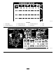
Locating the Fuses Jump-Starting the Machine The fuses in the electrical system are located under the seat (Figure 36). If you need to jump start the machine, you can use the alternate-positive post (located on the starter solenoid) instead of the positive battery post (Figure 38). g002735 Figure 38 1. Alternate-positive post g195277 Figure 36 1. Diagnostic lights, and glow—7.5 A 5. Lights and leak detector—15 A 2. Reel engage, lift/lower, fan—7.5 A 3. Lift reel, E-reel enable, and over temp—7.
Drive System Maintenance Checking the Tire Pressure Service Interval: Before each use or daily Vary the tire pressure for all 3 wheels, depending upon your turf conditions, from a minimum of 83 to a maximum of 110 kPa (12 psi to 16 psi). Checking the Torque of the Wheel Nuts g014616 Figure 39 Service Interval: After the first hour 1. Eccentric 2. Locknut After the first 10 hours Every 200 hours WARNING Failure to maintain proper torque of the wheel nuts could result in personal injury.
Adjusting the Mowing Speed The mow speed is set to 3.8 mph at the factory. You can adjust the forward moving speed from 0 to 8 km/h (0 to 5 mph). 1. Loosen the jam nut on the trunnion bolt (Figure 41). 2. Loosen the nut securing the lock and mow brackets on the pedal pivot. g015494 Figure 40 1. Pedal stop 1. Put the functional-control lever in the TRANSPORT position and loosen the locknut securing the pedal stop to the floor plate (Figure 40). 2.
Brake Maintenance Hydraulic System Maintenance Burnishing the Brakes Service Interval: Yearly Hydraulic System Safety Firmly apply the brakes and drive the machine at mowing speed until the brakes are hot, as indicated by their smell. You may need to adjust the brakes after the break-in period; refer to Burnishing the Brakes (page 41).
products only from reputable manufacturers who will stand behind their recommendation. High Viscosity Index/Low Pour Point Anti-wear Hydraulic Fluid, ISO VG 46 Material Properties: Viscosity, ASTM D445 cSt @ 40°C (104°F) 44 to 48 140 or higher Viscosity Index ASTM D2270 Pour Point, ASTM D97 -37°C to -45°C (-34°F to -49°F) Industry Specifications: Eaton Vickers 694 (I-286-S, M-2950-S/35VQ25 or M-2952-S) Note: Many hydraulic fluids are almost colorless, making it difficult to spot leaks.
Changing the Hydraulic Fluid and Filter and Checking the Hydraulic-Fluid Level (page 42). Service Interval: Every 800 hours—If you are not using the recommended hydraulic fluid or have ever filled the reservoir with an alternative fluid, change the hydraulic fluid, filter, and tank breather. Every 1,000 hours—If you are using the recommended hydraulic fluid, change the hydraulic-fluid filter. Every 2,000 hours—If you are using the recommended hydraulic fluid, change the hydraulic fluid. 4.
g229110 g229108 Figure 46 Leak Alert! Figure 44 Before Starting (fluid cold) 5. Warning buzzer—no sound 6. Fluid level (cold) 1. Float switch (down—closed) Fluid level down 118 to 177 ml (4 to 6 oz) 3. Overflow tube 7. Solenoid-return valve (open) 2. Warning buzzer 4. Leak-detector tank 8. Float switch (raised—open) 1. Filler plug 2. Filler neck 3. Fluid level (warm) Checking the System Operation 1. With ignition switch in the ON position, move the leak detector switch rearward and hold.
Cutting Unit Maintenance Blade Safety A worn or damaged blade or bedknife can break, and a piece could be thrown toward you or bystanders, resulting in serious personal injury or death. • Inspect the blades and bedknives periodically for excessive wear or damage. • Use care when checking the blades. Wear gloves and use caution when servicing them. Only replace or backlap the blades and bedknives; never straighten or weld them.
Installing the Electrical Counterweights Secure the electrical counterweight to the existing counterweight with 2 capscrews as shown in Figure 49. g014602 Figure 50 1. Footrest—closed 3. 4. 2. Footrest—open Position the cutting unit under the center suspension arm. With the latches on the suspension-arm bar pointing up (i.e., open) (Figure 51), push the suspension arm down so that the bar fits over the bar across the top of the cutting unit (Figure 52). g036342 Figure 49 1. Capscrew 3.
5. Removing the Cutting Units Close the latches down and around the cutting-unit bar and lock them in place (Figure 51). 1. Note: You can hear a click and feel when the Disconnect the cutting unit power disconnect couplers; refer to Cutting Unit Power Disconnect Connectors (page 22). latches are properly locked in place. 6. 7. CAUTION Coat the spline shaft of the cutting unit motor with clean grease (Figure 53).
Backlapping the Reels WARNING Contact with the reels or other moving parts can result in personal injury. • Keep your fingers, hands, and clothing away from the reels or other moving parts. • Never attempt to turn the reels by hand or foot while the engine is running. g036124 Figure 55 Note: When sharpening, setting the 1.
Storage needed. Move the cutting-unit reel speed control to the desired mowing position. If you wish to store the machine for a long period of time, the perform following steps: Storage Safety • Shut off the machine, remove the key, and wait for all movement to stop before you leave the operator’s position. Allow the machine to cool before adjusting, servicing, cleaning, or storing it.
10. If possible, store the machine in a warm, dry location.
Notes:
Notes:
EEA/UK Privacy Notice Toro’s Use of Your Personal Information The Toro Company (“Toro”) respects your privacy. When you purchase our products, we may collect certain personal information about you, either directly from you or through your local Toro company or dealer.
California Proposition 65 Warning Information What is this warning? You may see a product for sale that has a warning label like the following: WARNING: Cancer and Reproductive Harm—www.p65Warnings.ca.gov. What is Prop 65? Prop 65 applies to any company operating in California, selling products in California, or manufacturing products that may be sold in or brought into California.
The Toro Warranty Two-Year or 1,500 Hours Limited Warranty Conditions and Products Covered Parts The Toro Company and its affiliate, Toro Warranty Company, pursuant to an agreement between them, jointly warrant your Toro Commercial product (“Product”) to be free from defects in materials or workmanship for 2 years or 1,500 operational hours*, whichever occurs first. This warranty is applicable to all products with the exception of Aerators (refer to separate warranty statements for these products).