Form No. 3416-956 Rev A Greensmaster® 3320 TriFlex® Traction Unit Model No. 04530—Serial No. 400000000 and Up Register at www.Toro.com.
This product complies with all relevant European directives; for details, please see the separate product specific Declaration of Conformity (DOC) sheet. WARNING CALIFORNIA Proposition 65 Warning This product contains a chemical or chemicals known to the State of California to cause cancer, birth defects, or reproductive harm. The engine exhaust from this product contains chemicals known to the State of California to cause cancer, birth defects, or other reproductive harm. g014685 Figure 1 1.
Contents Checking the Tire Pressure............................... 37 Checking the Torque of the Wheel Nuts .............................................................. 37 Adjusting the Transmission for Neutral.............. 37 Adjusting the Transport Speed.......................... 38 Adjusting the Mowing Speed ............................ 38 Brake Maintenance ............................................. 39 Adjusting the Brakes......................................... 39 Hydraulic System Maintenance ..
Safety • Do not operate the machine without all guards This machine has been designed in accordance with EN ISO 5395:2013 and ANSI B71.4-2012 and meets these standards when you add the appropriate weight kit. • • General Safety • This product is capable of amputating hands and feet and of throwing objects. Always follow all safety instructions to avoid serious personal injury. and other safety protective devices in place and working on the machine. Keep clear of any discharge opening.
decal115-8226 115-8226 1. Tipping hazard—read the Operator's Manual; always wear a seat belt when operating; do not remove the rollover protection system (ROPS). decal117-2718 117–2718 decal119-9346 119-9346 1. Press the pedal to unlock. 2. Read the Operator's Manual for more information.
decal132-9548 132-9548 1. Engine speed—fast 7. Reel speed—neutral 2. Engine speed—slow 8. Reel—transport 9. Reel—mow 3. Lower and engage the reels 4. Raise and disengage the reels 10. Reel—backlaping 5. Reel speed—fast 11. Move forward 6. Reel speed—slow decal132-9550 132-9550 1. Choke 3. Engine—run 2. Engine—start 4.
decalbatterysymbols Battery Symbols Some or all of these symbols are on your battery. 1. Explosion hazard decal131-2046 131-2046 6. Keep bystanders a safe distance from the battery. 2. No fire, open flame, or smoking 7. Wear eye protection; explosive gases can cause blindness and other injuries. 3. Caustic liquid/chemical burn hazard 4. Wear eye protection. 8. Battery acid can cause blindness or severe burns. 9. Flush eyes immediately with water and get medical help fast. 5.
decal115-8156 115-8156 1. Reel height 3. 8–Blade cutting unit 5. 14–Blade cutting unit 7. Fast 2. 5–Blade cutting unit 4. 11–Blade cutting unit 6. Reel speed 8.
Setup Loose Parts Use the chart below to verify that all parts have been shipped. Procedure Description 1 2 3 4 5 6 7 8 9 10 11 12 Use Qty. Roll bar Bolt (1/2 x 3-3/4 inches) Flange-nut (1/2 inch) Seat Seat wiring harness Steering wheel Locknut (1-1/2 inches) Washer Steering-wheel cap 1 4 4 1 1 1 1 1 1 No parts required – Activate and charge the battery. No parts required – Install the optional oil cooler.
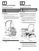
1 2 Installing the Roll Bar Installing the Seat Parts needed for this procedure: Parts needed for this procedure: 1 Roll bar 1 Seat 4 Bolt (1/2 x 3-3/4 inches) 1 Seat wiring harness 4 Flange-nut (1/2 inch) Procedure Procedure Note: Mount the seat in the front set of mounting 1. Remove the top crate support from the crate. 2. Remove the roll bar from the crate. 3.
the seat moves, and connect it to the port on the bottom of the seat. 4 3 Activating and Charging the Battery Installing the Steering Wheel No Parts Required Procedure Parts needed for this procedure: 1 Steering wheel 1 Locknut (1-1/2 inches) 1 Washer 1 Steering-wheel cap Use only electrolyte (1.265 specific gravity) to fill the battery initially.
WARNING Battery terminals or metal tools could short against metal tractor components causing sparks. Sparks can cause the battery gasses to explode, resulting in personal injury. • When removing or installing the battery, do not allow the battery terminals to touch any metal parts of the tractor. • Do not allow metal tools to short between the battery terminals and metal parts of the tractor. g032705 Figure 7 1. Electrolyte Important: Failure to correctly activate the 4. 5.
g005098 Figure 8 g015492 Figure 9 1. Negative (-) 1. Flange bolt 2. Positive (+) 3. Suspension-arm bar 2. Grass-basket hook 5 7 Installing the Oil Cooler (optional) Installing the Cutting Units Parts needed for this procedure: No Parts Required Procedure If you are operating the machine in hot climates, where the ambient temperature is above 29° C (85° F), or using it for heavy-duty use (mowing other than greens, such as fairways or verticutting), install a Hydraulic Oil Cooler Kit, Part No.
8 11 Setting the Clip-Control Feature Reducing the Tire Pressure No Parts Required No Parts Required Procedure Procedure The tires are over-inflated at the factory for shipping purposes. Reduce the pressure to the proper levels before starting the machine. Refer to Checking the Tire Pressure (page 37).
Product Overview g014603 Figure 11 1. Traction pedal—forward 3. Steering-arm-locking pedal 2. Taction pedal—reverse g014674 Figure 10 1. Engine 5. Steering wheel 2. Roll bar 6. Traction pedal 3. Control panel 7. Footrest 4. Seat 8. Cutting units Controls g005105 Traction Pedal Figure 12 The traction pedal (Figure 11) has 3 functions: to make the machine move forward, to move it backward, and to stop the machine.
Ignition Switch Note: You cannot stop the engine using the throttle lever. Insert the key into the switch (Figure 13) and turn it clockwise as far as possible to the START position to start the engine. Release the key as soon as the engine starts; the key moves to the ON position. Turn the key counterclockwise to the OFF position to shut off the engine. Parking-Brake Lever Pull up on the brake lever (Figure 14) to set the parking brake.
• FUNCTIONAL CONTROL STATUS —transport mode is indicated by a rabbit and mow mode is indicated by a turtle. • ENGINE OIL PRESSURE light—this icon appears if the engine oil pressure drops below a safe level. • MENU ACCESS/BACK button—press this button to access the InfoCenter menus. You can use it to back out of any menu you are currently using. • DOWN button—use this button to scroll down menus. • RIGHT button—use this button to open a menu where a right arrow indicates additional content.
SERVICE Menu Item Description HOURS Lists the total number of hours that the machine, engine, reels, backlap, and fan have been on, as well as the number of hours the machine has been transported and overheated. COUNTS Lists the number of preheats and starts the machine has experienced. BACKLAP Turns backlapping ON/OFF (once ON you can turn backlapping Off with this setting or by turning off the ignition key). BLADE COUNT Set the number of blades in each reel.
Adjusting the Tap-off Delay The tap-off delay feature allows the cutting units to turn off without raising, and you may adjust it with the InfoCenter. The delay setting represents the maximum time for the raise/lower joystick to remain in the raise position to activate this feature. The factory default setting is 1 which disables this feature. Increment Number Delay Time (Seconds) 1 Off 2 0.050 3 0.100 4 0.150 5 0.200 6 0.250 7 0.300 8 0.350 9 0.400 10 0.450 g014736 Figure 17 4.
Cutting Unit Power Disconnect Connectors Note: If you need additional adjustment on the seat, you can remove the 4 nuts securing the seat slide rails to the base and move the seat slide rails to the second set of mounting holes provided. Before installing, removing, or working on the cutting units, disconnect the cutting units from the power supply by separating the cutting unit power disconnect connectors (Figure 20), located at the base of the rollover bar on the left side of the traction unit.
Attachments/Accessories Operation A selection of Toro approved attachments and accessories is available for use with the machine to enhance and expand its capabilities. Contact your Authorized Service Dealer or Distributor or go to www.Toro.com for a list of all approved attachments and accessories. Note: Determine the left and right sides of the machine from the normal operating position.
Filling the Fuel Tank Performing Daily Maintenance • Fuel tank capacity: 26.6 L (7 US gallons) • Recommended Fuel: Before starting the machine each day, perform the following procedures: • Check the engine-oil level—refer to Checking the Engine Oil (page 33). • Check the hydraulic-fluid level—refer to Checking the Hydraulic-Fluid Level (page 39). • Check the reel-to-bedknife contact—refer to Checking the Reel-to-Bedknife Contact (page 46).
• • • • • • • • injury or death. Operating the machine on any slope requires extra caution. vibration in the machine. Make all necessary repairs before resuming operation. Slow down and use caution when making turns and crossing roads and sidewalks with the machine. Always yield the right-of-way. Disengage the drive to the cutting unit and shut off the engine before adjusting the height of cut (unless you can adjust it from the operating position).
1. 2. 3. 4. 5. 6. move the functional-control lever to the NEUTRAL position. Sit on the seat, lock the parking brake, disengage the raise/lower mow control and move the functional-control lever to the NEUTRAL position. Remove your foot from the traction pedal and make sure the pedal is in the NEUTRAL position. Move the choke lever to the CLOSED position (only when starting a cold engine) and the throttle lever to the HALF THROTTLE position.
3. Sit on the seat, move the traction pedal to the NEUTRAL position, move the functional-control lever to the NEUTRAL position, and engage the parking brake. 4. Move the functional-control lever to the MOW position or the TRANSPORT position and try to start the engine. Driving the Machine without Mowing Ensure that the cutting units are fully raised. Move the functional-control lever to the TRANSPORT position. Use the brakes to slow the machine while going down steep hills to avoid loss of control.
5. units, drive directly off the green, and stop the machine in an area away from the green. Determine the cause of the leak and correct the problem. As the front edges of the baskets cross the edge of the green, move the raise/lower mow lever rearward and hold it until all the cutting units have risen. This stops the reels and lifts the cutting units. 8.
Inspecting and Cleaning after Mowing After Operation Safety General Safety After mowing, thoroughly wash the machine with a garden hose without a nozzle so that excessive water pressure does not contaminate and damage the seals and bearings. Do not wash a warm engine or electrical connections with water. • Clean grass and debris from the cutting units, drives, mufflers, cooling screens, and engine to help prevent fires. Clean up oil or fuel spills.
Towing the Machine In case of an emergency, you can tow the machine for up to 0.4 km (1/4 mile). Important: Do not tow the machine faster than 3 to 5 km/h (2 to 3 mph) to avoid damaging the drive system. If you must move the machine more than 0.4 km (1/4 mile), transport it on a truck or trailer. 1. Locate the bypass valve on the pump and rotate it so that the slot is vertical (Figure 23). g014627 Figure 23 1. Bypass valve-slot shown in closed (horizontal) position 2.
Maintenance WARNING Failure to properly maintain the machine could result in premature failure of machine systems causing possible harm to you or bystanders. Keep the machine well maintained and in good working order as indicated in these instructions. Note: Determine the left and right sides of the machine from the normal operating position. Note: Download a free copy of the electrical or hydraulic schematic by visiting www.Toro.com and searching for your machine from the Manuals link on the home page.
Recommended Maintenance Schedule(s) Maintenance Service Interval Maintenance Procedure After the first hour • Check the torque of the wheel nuts. After the first 10 hours • Check the torque of the wheel nuts. After the first 25 hours • Change the engine oil and filter. After the first 50 hours • Change the hydraulic-fluid filter. • Check the engine speed (at idle and full throttle). Before each use or daily • • • • • • • Check the safety-interlock system. Inspect and cleanup after mowing.
Daily Maintenance Checklist Duplicate this page for routine use. Maintenance Check Item For the week of: Mon. Tues. Wed. Thurs. Fri. Check the safety-interlock operation. Check the instrument operation Check the leak-detector alarm. Check the brake operation. Check the fuel level. Check the hydraulic-fluid level. Check the engine-oil level. Clean the engine, air-cooling fins. Inspect the air-filter pre-cleaner. Check any unusual engine noises. Check the reel-to-bedknife adjustment.
Pre-Maintenance Procedures Lubrication Pre-Maintenance Safety Service Interval: Every 400 hours • Before adjusting, cleaning, repairing, or leaving Lubricate the grease fitting with No. 2 lithium grease. Greasing the Machine the machine, do the following: 1. – Park the machine on a level surface. – Move the throttle switch to the low-idle position. Wipe the grease fitting clean so foreign matter cannot be forced into the bearing or bushing (Figure 24). – Disengage the cutting units.
Engine Maintenance Engine Safety • Shut off the engine before checking the oil or adding oil to the crankcase. • Do not change the governor speed or overspeed the engine. Servicing the Air Cleaner Service Interval: Every 50 hours—Service the air-cleaner foam element (more frequently when operating conditions are dusty or dirty). g005126 Figure 26 1. Foam element Every 100 hours—Service the air-cleaner paper element (more frequently when operating conditions are dusty or dirty). 1. 2. Paper element 5.
3. Apply a light coat of clean oil to the new filter gasket. 4. Screw the filter on by hand until the gasket contacts the filter adapter, then tighten it 3/4 to 1 turn further. Do not overtighten it. 5. Add oil to the crankcase; refer to Checking the Engine Oil (page 33). 6. Dispose of the oil filter and used oil properly. Replacing the Spark Plugs g005111 Service Interval: Every 800 hours Figure 27 1. Dipstick The recommended air gap is 0.76 mm (0.030 inch) 2. Filler cap 4.
Fuel System Maintenance Electrical System Maintenance Replacing the Fuel Filter Electrical System Safety Service Interval: Every 800 hours (Sooner if the fuel flow is restricted) • Disconnect the battery before repairing the machine. Disconnect the negative terminal first and the positive last. Connect the positive terminal first and the negative last. An in-line filter is incorporated into the fuel line between the fuel tank and carburetor (Figure 30).
Servicing the Battery Locating the Fuses Properly maintain the battery electrolyte and keep the top of the battery clean. Store the machine in a cool place to prevent the battery from running down. The fuses in the electrical system are located under the seat (Figure 31). Check the electrolyte level every 50 operating hours or, if machine is in storage, every 30 days. DANGER Battery electrolyte contains sulfuric acid which is a deadly poison and causes severe burns.
Drive System Maintenance Checking the Tire Pressure Service Interval: Before each use or daily Vary the tire pressure for all 3 wheels, depending upon your turf conditions, from a minimum of 83 to a maximum of 110 kPa (12 psi to 16 psi). Checking the Torque of the Wheel Nuts g014616 Figure 32 1. Eccentric WARNING 2. Locknut Failure to maintain proper torque of the wheel nuts could result in personal injury. B.
Adjusting the Transport Speed 3. Tighten the locknut securing the pedal stop. Adjusting the Mowing Speed Obtaining the Maximum Transport Speed The mow speed is set to 3.8 mph at the factory. The traction pedal is adjusted for maximum-transport speed at the factory, but you may need to adjust it if the pedal reaches full stroke before it contacts the pedal stop, or if you want to a decrease the transport speed. The forward moving speed can be adjusted from 0 to 8 km/h (0 to 5 mph).
Brake Maintenance Hydraulic System Maintenance Adjusting the Brakes Hydraulic System Safety If the brake fails to hold the machine while parked, you can adjust the brakes using the bulkhead fitting near the brake drum; contact your Authorized Service Distributor or refer to the Service Manual for more information. • Ensure that all hydraulic-fluid hoses and • Note: Burnish the brakes annually; refer to 12 Burnishing the Brakes (page 14).
Filling the Hydraulic Tank High Viscosity Index/Low Pour Point Anti-wear Hydraulic Fluid, ISO VG 46 1. Material Properties: Viscosity, ASTM D445 cSt @ 40° C 44 to 48 cSt @ 100° C 7.9 to 8.5 Viscosity Index ASTM D2270 140 to 160 Pour Point, ASTM D97 -34° F to -49° F Position the machine on a level surface. Note: Ensure that the machine has cooled down so the oil is cold. 2.
Changing the Hydraulic Fluid and Filter Service Interval: After the first 50 hours Every 800 hours If the fluid becomes contaminated, have your Toro distributor flush the system. Contaminated fluid looks milky or black when compared to clean fluid. 1. Clean the area around the filter mounting area (Figure 37). Place a drain pan under the filter and remove the filter. g223376 Figure 36 1. Dipstick 3. Remove the dipstick and wipe it with a clean rag, then screw the dipstick back into the tank. 4.
Checking the Hydraulic Lines and Hoses WARNING Hydraulic fluid escaping under pressure can penetrate skin and cause injury. • Ensure that all hydraulic fluid hoses and lines are in good condition and all hydraulic connections and fittings are tight before applying pressure to the hydraulic system. • Keep your body and hands away from pinhole leaks or nozzles that eject high-pressure hydraulic fluid. g020735 Figure 38 Before Starting (fluid cold) • Use cardboard or paper to find hydraulic leaks. 1.
g005510 Figure 41 g020737 Figure 40 Leak Alert! 1. Clean rod or screwdriver 3. Warning buzzer 2. Press down on switch 1. Float-down switch closed Fluid level down 118 to 177 ml (4 to 6 oz) 3. Fluid level (warm) 4. Release the float; the alarm should stop sounding. 5. Install the hydraulic-tank cap. 6. Move the ignition switch to the OFF position. 2. Warning buzzer Checking the System Operation 1. 2. With ignition switch in the ON position, move the leak detector switch rearward and hold.
Cutting Unit Maintenance Installing the Electrical Counterweights Cutting Unit Safety Secure the electrical counterweight to the existing counterweight with 2 cap screws as shown in Figure 43. A worn or damaged blade or bed-knife can break, and a piece could be thrown at you or bystanders, resulting in serious personal injury or death. • Inspect the blades and bed-knives periodically for excessive wear or damage. • Use care when checking the blades. Wear gloves and use caution when servicing them.
5. Close the latches down and around the cutting-unit bar and lock them in place (Figure 45). Note: You can hear a click and feel when the latches are properly locked in place. g014602 6. Coat the spline shaft of the cutting unit motor with clean grease (Figure 47). 7. Insert the motor into the left side of the cutting unit (as viewed from the operator's position) and pull the motor retaining bar on the cutting unit toward the motor until you hear a click from both sides of the motor (Figure 47).
Removing the Cutting Units 1. Disconnect the cutting unit power disconnect couplers; refer to Cutting Unit Power Disconnect Connectors (page 20). CAUTION If you do not disconnect the power to the cutting units, someone could accidentally start the cutting unit, causing serious injury to hands and feet. g036124 Figure 49 Always separate the cutting unit power disconnect couplers before working on the cutting units. 2. 3.
Backlapping the Reels 15. WARNING Contact with the reels or other moving parts can result in personal injury. • Keep your fingers, hands, and clothing away from the reels or other moving parts. • Never attempt to turn the reels by hand or foot while the engine is running. 1. Position the machine on a level surface, lower the cutting units, shut off the engine, and engage the parking brake. 2. Remove the plastic cover to the left side of the seat. 3.
Storage If you wish to store the machine for a long period of time, the following steps should be performed prior to storage: 1. Remove accumulations of dirt and old grass clippings. Sharpen the reels and bedknives, if necessary; refer to the cutting unit Operator's Manual. Use a rust preventive on bedknives and reel blades. Grease and oil all lubrication points. 2. Block up the wheels to remove any weight on the tires. 3.
Notes:
Notes:
European Privacy Notice The Information Toro Collects Toro Warranty Company (Toro) respects your privacy. In order to process your warranty claim and contact you in the event of a product recall, we ask you to share certain personal information with us, either directly or through your local Toro company or dealer. The Toro warranty system is hosted on servers located within the United States where privacy law may not provide the same protection as applies in your country.
The Toro Warranty A Two-Year Limited Warranty Conditions and Products Covered The Toro Company and its affiliate, Toro Warranty Company, pursuant to an agreement between them, jointly warrant your Toro Commercial product (“Product”) to be free from defects in materials or workmanship for two years or 1500 operational hours*, whichever occurs first. This warranty is applicable to all products with the exception of Aerators (refer to separate warranty statements for these products).