
Operator's Manual


5
1. The cutting unit is shipped without a front roller. Install
the roller using the loose parts supplied with the cutting
unit and installation instructions included with the
roller.
2. Ensure that all nuts and bolts are securely fastened.
3. For cutting units that will be mounted on a traction unit
with a serial number prior to 240000001, the proper lift
link must be obtained and installed.
Hoop link, part No. 105-5740 and (2) capscrews, part no.
33115-025 are required for installation on the Greensmaster
3000, 3000–D, 3050, 3100 and 3150 traction units.
• Install hoop link to top of cutting unit with (2)
capscrews. Torque capscrews to 25–30 ft–lbs.
(34–40 N⋅m) (Fig. 2).
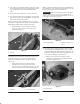
1
Figure 2
1. Hoop link
Chain link, part no. 106–2601, mounting bracket, part no.
105-5738 and (2) capscrews, part no. 33115-025 are
required for installation on the Greensmaster 3250-D
traction unit.
• Install chain link to top of cutting unit with
mounting bracket and (2) capscrews. Torque
capscrews to 25–30 ft–lbs. (34–40 N⋅m). Large end
of link to hook on traction unit suspension (Fig. 3).
2
1
Figure 3
1. Chain link 2. Mounting bracket
Note: An optional Lift Hook, Toro Part No. 106-6938 may
be used in place of the chain link, if desired (Fig. 2). It may
be obtained from your local Toro Distributor.
Important Whenever the cutting unit has to be tipped
to expose bedknife/reel, prop up rear of cutting unit to
make sure nuts on back end of bedbar adjusting screws are
not resting on work surface (Fig. 4).
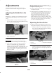
1
2
Figure 4
1. Prop (not provided) 2. Bedknife adjusting screw
nut (2)
4. All cutting units are shipped with the counter weight
mounted to the left end and the motor mount and drive
coupler mounted to the right end of the cutting unit. To
mount the cutting unit in the right front position, on the
Greensmaster 3250-D proceed as follows:
A. Remove the 2 capscrews securing the counter
weight to the left end of the cutting unit. Remove
the counter weight (Fig. 5).
1
Figure 5
1. Counter weight