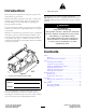
Form No. 3389-201 Rev A 8, 11, and 14-Blade DPA Reel Mower Greensmaster® 3300/3400 Series Traction Unit Model No. 04613—Serial No. 315000001 and Up Model No. 04614—Serial No. 315000001 and Up Model No. 04615—Serial No. 315000001 and Up Register at www.Toro.com.
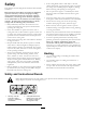
Figure 2 Introduction 1. Safety alert symbol This cutting unit is designed for cutting turf on greens and small fairways of golf courses. This manual uses 2 words to highlight information. Important calls attention to special mechanical information and Note emphasizes general information worthy of special attention. Read this information carefully to learn how to operate and maintain your product properly and to avoid injury and product damage.
Safety • If the cutting blades strike a solid object or the unit vibrates abnormally, stop and shut the engine off. Check the cutting units for damaged parts. Repair any damage before restarting and operating the cutting units. This machine has been designed in accordance with EN ISO 5395:2013.
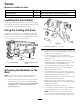
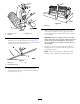
Setup Media and Additional Parts Description Use Qty. Operator's Manual 1 Read before installing and operating cutting unit Parts catalog 1 Use to reference part numbers Installing the Front Roller The cutting unit is shipped without a front roller. Install the roller using the loose parts supplied with the cutting unit and installation instructions included with the roller.
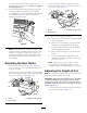
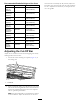
to the reel and counterclockwise rotation move the bedknife edge away from the reel. Do not over tighten the adjusting screws. Position the spacer below the sideplate mounting flange when height of cut settings range from 3 to 25 mm (1/8 to 1 inch) (Figure 7). 11. Test the cutting performance by inserting a long strip of cutting performance paper (Toro part number 125-5610) between the reel and bedknife, perpendicular to the bedknife (Figure 5). Slowly rotate the reel forward; it should cut paper.
Figure 10 1. Gauge bar G020095 4. Rotate the adjusting bolt on the height-of-cut arms until the front roller contacts the gauge bar. Adjust both ends of the roller until the entire roller is parallel to the bedknife. Figure 8 1. Height-of-cut arm 3. Adjusting bolt 2. Locknut Important: When set properly, the rear and front rollers will contact the gauge bar and the bolt head will be snug against the bedknife. This ensures that the height-of-cut is identical at both ends of the bedknife. 2.
Recommended Bedknife/Height-of-Cut Chart Bedknife Part Number when the turf is extremely dry. By contrast, adjust the bar further away from the reel when the turf conditions are wet. Adjust the bar whenever you sharpen the reel on a reel grinder. Height-of-Cut Edgemax Micro-cut (Standard) 115-1880 1.5–4.7 mm (0.062–0.188 inch) Edgemax Tournament (Optional) 115-1881 3.1–12.7 mm (0.125–0.500 inch) Micro-cut (Optional) 93-4262 1.5–4.7 mm (0.062–0.188 inch) Tournament (Optional) 93-4263 3.1–12.
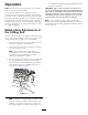
Product Overview Specifications Tractors These cutting units will mount on the Greensmaster 3300 and 3400 Traction Units. Height-of-Cut Cutting height is adjusted on the front roller by two vertical screws and held by two locking cap screws Height-of-Cut Range Standard bench height-of-cut range is 1.6 mm (0.062 inch) to 12.7 mm (0.500 inch). Bench height-of-cut range with the High Height-of-Cut Kit installed is 7 mm (0.285 inch) to 25 mm (1.00 inch).
Operation Toro Manual for Sharpening Reel and Rotary Mowers, Form No. 09168SL). Note: Determine the left and right sides of the machine from the normal operating position. Important: Light contact is preferred at all times. If you do not maintain light contact, the bedknife and reel edges will not sufficiently self-sharpen and will dull after a period of operation. If you maintain excessive contact, the bedknife and reel will wear quicker, wear unevenly, and the quality of cut may be adversely affected.
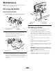
Maintenance Note: Determine the left and right sides of the machine from the normal operating position. Servicing the Bedbar Removing the Bedbar 1 1. Turn the bedbar adjuster screw counterclockwise, to back the bedknife away from the reel (Figure 13). G020096 Figure 15 1. Bedbar bolt 2. Locknut Figure 13 1. Bedbar adjusting screw 3. Bedbar 2. Spring tension nut 4. Washer 3. Steel washer 4. Nylon washer Assembling the Bedbar 1.
2 1 g014642 Figure 16 1. Spring tension nut 2. Spring 7. Adjust the bedknife to the reel; refer to Adjusting the Bedknife to the Reel. Backlapping the Reel DANGER Contact with the reel or other moving parts can result in personal injury. Keep fingers, hands, and clothing away from the reels or other moving parts. • Stay away from the reel while backlapping. • Never use a short handled paint brush for backlapping. Part No.
Notes: 12
Notes: 13
Notes: 14
Declaration of Incorporation The Toro Company, 8111 Lyndale Ave. South, Bloomington, MN, USA declares that the following unit(s) conform(s) to the directives listed, when installed in accordance with the accompanying instructions onto certain Toro models as indicated on the relevant Declarations of Conformity. Model No. Serial No.
Toro General Commercial Product Warranty A Two-Year Limited Warranty Conditions and Products Covered The Toro Company and its affiliate, Toro Warranty Company, pursuant to an agreement between them, jointly warrant your Toro Commercial product (“Product”) to be free from defects in materials or workmanship for two years or 1500 operational hours*, whichever occurs first. This warranty is applicable to all products with the exception of Aerators (refer to separate warranty statements for these products).