Form No. 3366-561 Rev B 8, 11, and 14-Blade DPA Reel Mower for Greensmaster® 3300/3400 Series Traction Units Model No. 04613—Serial No. 311000001 and Up Model No. 04614—Serial No. 311000001 and Up Model No. 04615—Serial No. 311000001 and Up To register your product or download an Operator's Manual or Parts Catalog at no charge, go to www.Toro.com.
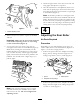
Introduction Figure 2 Read this information carefully to learn how to operate and maintain your product properly and to avoid injury and product damage. You are responsible for operating the product properly and safely. 1. Safety alert symbol This manual uses 2 other words to highlight information. Important calls attention to special mechanical information and Note emphasizes general information worthy of special attention. You may contact Toro directly at www.Toro.
Safety advisable and required by some local ordinances and insurance regulations. Hazard control and accident prevention are dependent upon the awareness, concern, and proper training of the personnel involved in the operation, transport, maintenance, and storage of the machine. Improper use or maintenance of the machine can result in injury or death. To reduce the potential for injury or death, comply with the following safety instructions.
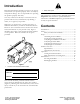
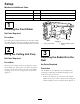
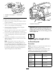
Setup Media and Additional Parts Description Use Qty. Operator’s Manual 1 Read before installing and operating cutting unit Parts catalog 1 Use to reference part numbers Certification of compliance 1 Save for future reference 1 Installing the Front Roller No Parts Required 2 Procedure 2 1 g014596 The cutting unit is shipped without a front roller. Install the roller using the loose parts supplied with the cutting unit and installation instructions included with the roller. Figure 3 1.
4. Check for light contact at the other end of the reel using paper and adjust it as required. 5. After the adjustment is accomplished, check to see if the reel can pinch paper when inserted from the front and cut the paper when inserted at a right angle to the bedknife (Figure 5). 1 Note: It should be possible to cut the paper with minimum contact between the bedknife and the reel blades.
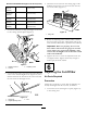
Figure 7 1. Sideplate mounting flange 2. Spacer 3. Roller bracket To adjust rear roller proceed as follows: 1. Raise the rear of the cutting unit and place a block under the bedknife. Figure 8 1. Sideplate mounting bolts 2. Remove the 2 nuts securing each roller bracket and spacer to each sideplate mounting flange.
3. Hook the screw head onto the cutting edge of the bedknife and rest the rear end of the bar onto the rear of the roller (Figure 11). Recommended Bedknife/Height of Cut Chart (cont'd.) Extended Micro-cut (Optional) 108-4303 0.062–0.188 inch (1.5–4.7 mm) Extended Tournament (Optional) 108-4302 0.125–0.500 inch (3.1–12.7 mm) Low-cut (Optional) 93-4264 0.188–1.00 inch (4.7–25.4 mm) High-cut (Optional) 94-6392 0.312–1.00 inch (7.9–25.4 mm) Fairway (Optional) 63-8600 0.375–1.00 inch (9.5–25.
1 g014643 Figure 12 1. Cut-off bar 2. Insert a 0.060 inch feeler gauge between the top of the reel and the bar and tighten the screws. Ensure that the bar and reel are equal distance apart across the complete reel. Note: The bar is adjustable to compensate for changes in turf conditions. The bar should be adjusted closer to the reel when the turf is extremely dry. By contrast, adjust the bar further away from the reel when the turf conditions are wet.
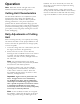
Product Overview Specifications Tractors These cutting units will mount on the Greensmaster 3300 and 3400 Traction Units. Height of Cut Cutting height is adjusted on the front roller by two vertical screws and held by two locking cap screws Height Of Cut Range Standard bench height of cut range is .062 inch (1.6 mm) to .500 inch (12.7 mm). Bench height of cut range with the High Height of Cut Kit installed is .285 inch (7 mm) to 1.00 inch (25 mm).
Operation bedknife. If a file is occasionally run across the front edge to remove this burr, improved cutting can be obtained. After extended running, a ridge will eventually develop at both ends of the bedknife. These notches must be rounded off or filed flush with the cutting edge of the bedknife to ensure smooth operation. Note: Determine the left and right sides of the machine from the normal operating position.
Maintenance stamped steel washers on each end of the bedbar (Figure 15). Note: Determine the left and right sides of the machine from the normal operating position. Servicing the Bedbar Removing the Bedbar 1. Turn the bedbar adjusting screw, counterclockwise, to back the bedknife away from the reel (Figure 13). 1 3 4 1 g014410 Figure 15 1. Bedbar bolt 2. Nut 2 3. Steel washer 4. Nylon washer Assembling the Bedbar 1.
operation is completed. This will remove any burrs or rough edges that may have built up on the cutting edge. 2 1 g014642 Figure 16 1. Spring tension nut 2. Spring Backlapping the Reel DANGER Contact with the reel or other moving parts can result in personal injury. Keep fingers, hands, and clothing away from the reels or other moving parts. • Stay away from the reel while backlapping. • Never use a short handled paint brush for backlapping. Part No.
Notes: 13
Notes: 14
Notes: 15
The Toro Total Coverage Guarantee A Limited Warranty Conditions and Products Covered The Toro® Company and its affiliate, Toro Warranty Company, pursuant to an agreement between them, jointly warrant your Toro Commercial product (“Product”) to be free from defects in materials or workmanship for two years or 1500 operational hours*, whichever occurs first. This warranty is applicable to all products with the exception of Aerators (refer to separate warranty statements for these products).