
Operator's Manual
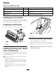
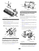
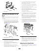
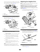
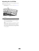

Figure9
1.Counterweight
AdjustingtheBedknifetothe
Reel
Note:Usethisprocedureforinitialsetupandaftergrinding,
backlapping,ordisassembly.Itisnotintendedasadaily
adjustment.
1.Positionthecuttingunitonaat,levelworksurface.
2.Tipthecuttingunittoexposethebedknifeandthe
reel.Makesurethenutsorthebackofthebedbar
adjustingscrewsarenotrestingonthework
surface(Figure10).
g026076
1
2
Figure10
1.Bedknifeadjustingscrew
2.Nut
3.Rotatethereelsothatabladecrossesthebedknifeedge
betweentherstandsecondbedknifescrewheadson
therightsideofthecuttingunit.
4.Putanidentifyingmarkonthebladewhereit
crossesthebedknifeedge;thiswillmakesubsequent
adjustmentseasier.
5.Insertthe.05mm(0.002inch)shimbetweenthe
markedbladeandthebedknifeedgeatthepointwhere
themarkedbladecrossesthebedknifeedge.
6.Turntherightbedbaradjustingscrewuntilyoufeel
lightpressure(i.e.drag)ontheshimbyslidingit
side-to-side.Removetheshim.
7.Fortheleftsideofthecuttingunit,slowlyrotatethe
reelsothattheclosestbladecrossesthebedknifeedge
betweentherstandsecondscrewheads.
8.Repeatsteps4through6fortheleftsideofthecutting
unitandleftbedbaradjustingscrew .
9.Repeatsteps5and6untillightdragisachievedon
boththerightandleftsidesofthecuttingunitutilizing
thesamecontactpoints.
Thebedknifeisnowparalleltothereel.
10.Toobtainlightcontactbetweenthereelandbedknife,
turneachbedbaradjustingscrewclockwise3clicks.
Note:Eachclickturnedonthebedbaradjusting
screwmovesthebedknife0.018mm(0.0007inches).
Clockwiserotationmovesthebedknifeedgecloser
tothereelandcounterclockwiserotationmovesthe
bedknifeedgeawayfromthereel.
11.Testthecuttingperformancebyinsertingalongstrip
ofcuttingperformancepaper(Toropartnumber
125-5610)betweenthereelandbedknife,perpendicular
tothebedknife(Figure11).Slowlyrotatethereel
forward;itshouldcutpaper
Figure11
Note:Ifexcessivecontact/reeldragisevidentitwill
beeithernecessarytobacklap,refacethefrontofthe
bedknife,orregrindthecuttingunittoachievethe
sharpedgesneededforprecisioncutting(Refertothe
ToroManualforSharpeningReelandRotaryMowers,
FormNo.09168SL).
AdjustingtheRearRoller
1.Adjusttherearrollerbrackets(Figure12orFigure13)
totheloworhighpositiondependingonthedesired
heightofcutrange.
6