
Operator's Manual
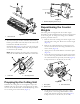

Positionthespacerabovethesideplatemountingange
(factorysetting)whenheightofcutsettingsrangefrom
1.6to6mm(1/16to1/4inch)(Figure12).
Figure12
1.Spacer3.Sideplatemountingange
2.Rollerbracket
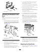
Positionthespacerbelowthesideplatemounting
angewhenheightofcutsettingsrangefrom3to25
mm(1/8to1inch)(Figure13).
Figure13
1.Spacer3.Sideplatemountingange
2.Rollerbracket
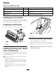
2.Toadjustrearrollerproceedasfollows:
A.Raisetherearofthecuttingunitandplaceablock
underthebedknife.
B.Removethe2nutssecuringeachrollerbracket
andspacertoeachsideplatemountingange.
C.Lowertherollerandscrewsfromthesideplate
mountingangesandspacers.
D.Placethespacersontothescrewsontheroller
brackets.
E.Securetherollerbracketandspacerstothe
undersideofthemountingangeswiththenuts
previouslyremoved.
Note:Thepositionoftherearrollertothereel
iscontrolledbythemachiningtolerancesofthe
assembledcomponentsandparallelingisnotrequired.
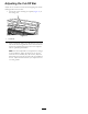
AdjustingtheHeight-of-Cut
Note:Forheights-of-cutgreaterthan0.953cm(0.375inch),
youmustinstallthehighheight-of-cutkit.
Important:Wheneverthecuttingunithastobetipped
toexposethebedknife/reel,propuptherearofthe
cuttingunittomakesurethenutsonthebackendof
thebedbaradjustingscrewsarenotrestingonthework
surface(Figure7).
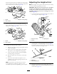
1.Loosenthelocknutssecuringtheheight-of-cutarmsto
thecuttingunitsideplates(Figure14).
G020074
Figure14
1.Height-of-cutarm
3.Adjustingbolt
2.Locknut
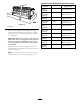
2.Loosenthenutonthegaugebarandsettheheight
adjustingbolttothedesiredheight-of-cut(Figure15).
Thedistancebetweenthebottomoftheboltheadand
thefaceofthebaristheheight-of-cut.
Figure15
1.Gaugebar
3.Nut
2.Heightadjustingbolt
3.Hooktheboltheadontothecuttingedgeofthe
bedknifeandresttherearendofthebarontotherear
oftheroller(Figure16).
7