Form No. 3376-588 Rev B 8, 11, and 14-Blade DPA Reel Mower Greensmaster® 3000 Series Traction Unit Model No. 04618—Serial No. 313000001 and Up Model No. 04619—Serial No. 313000001 and Up Model No. 04624—Serial No. 313000001 and Up Register at www.Toro.com.
Figure 2 Introduction 1. Safety alert symbol This cutting unit is designed for cutting turf on greens and small fairways of golf courses. This manual uses 2 words to highlight information. Important calls attention to special mechanical information and Note emphasizes general information worthy of special attention. Read this information carefully to learn how to operate and maintain your product properly and to avoid injury and product damage.
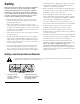
Safety and substantial shoes. Wearing safety glasses, safety shoes, and a helmet is advisable and required by some local ordinances and insurance regulations. Hazard control and accident prevention are dependent upon the awareness, concern, and proper training of the personnel involved in the operation, transport, maintenance, and storage of the machine. Improper use or maintenance of the machine can result in injury or death.
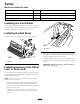
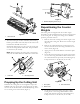
Setup Media and Additional Parts Description Use Qty. Ball stud 2 Mount to roller Operator's Manual 1 Read before installing and operating cutting unit Parts catalog 1 Use to reference part numbers Installing the Front Roller The cutting unit is shipped without a front roller. Install the roller using the loose parts supplied with the cutting unit and installation instructions included with the roller. Installing the Ball Studs Install a ball stud on each end of the front roller (Figure 3).
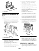
Figure 7 1. Bedknife adjusting screw nut (2) Repositioning the Counter Weights The cutting units are shipped with the counter weight mounted to the left end and the motor mount to the right end of the cutting unit. To change the cutting unit to different positions, proceed as follows: G020065 Figure 5 1. Offset lift hook 1. Remove the 2 bolts securing the counter weight to the left end of the cutting unit. Remove the counter weight (Figure 9).
. Turn the right bedbar adjusting screw until you feel light pressure (i.e. drag) on the shim by sliding it side-to-side. Remove the shim. 7. For the left side of the cutting unit, slowly rotate the reel so that the closest blade crosses the bedknife edge between the first and second screw heads. 8. Repeat steps 4 through 6 for the left side of the cutting unit and left bedbar adjusting screw. 9.
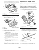
Adjusting the Height of Cut Position the spacer above the sideplate mounting flange (factory setting) when height of cut settings range from 1.6 to 6 mm (1/16 to 1/4 inch) (Figure 12). Note: For heights of cut greater than 1.270 cm (0.500 inch), you must install the high height of cut kit.
Adjusting the Cut-Off Bar Adjust the cut-off bar to ensure that the clippings are cleanly discharged from the reel area: 1. Loosen the screws securing the top bar (Figure 17) to the cutting unit. 1 Figure 16 1. Gauge bar 4. Rotate the adjusting bolt on the height-of-cut arms until the front roller contacts the gauge bar. Adjust both ends of the roller until the entire roller is parallel to the bedknife. g014643 Figure 17 1.
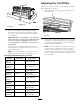
Product Overview Specifications. Tractors These cutting units will mount on the Greensmaster 3000, 3000-D, 3050, 3100, 3150, 3250-D, and 3150-Q Traction Units. Height of Cut Cutting height is adjusted on the front roller by two vertical bolts and held by two locking bolts. Height Of Cut Range Standard bench height-of-cut range is 1.6 mm (0.062 inch) to 12.7 mm (0.500 inch). Bench height-of-cut range with the High Height of Cut Kit installed is 7 mm (0.285 inch) to 25 mm (1.00 inch).
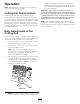
Operation bedknife, or regrind the cutting unit to achieve the sharp edges needed for precision cutting (Refer to the Toro Manual for Sharpening Reel and Rotary Mowers, Form No. 09168SL). Note: Determine the left and right sides of the machine from the normal operating position. Important: Light contact is preferred at all times. If you do not maintain light contact, the bedknife and reel edges will not sufficiently self-sharpen and will dull after a period of operation.
Maintenance Note: Determine the left and right sides of the machine from the normal operating position. Servicing the Bedbar Removing the Bedbar 1. Turn the bedbar adjuster screw counterclockwise, to back the bedknife away from the reel (Figure 19). g020056 Figure 21 1. Bedbar bolt 2. Locknut 3. Steel washer 4. Nylon washer Assembling the Bedbar 1. Install the bedbar, positioning the mounting ears between the washer and bedbar adjuster. 2.
Figure 22 1. Spring tension nut 2. Spring 7. Adjust the bedknife to the reel; refer to Adjusting the Bedknife to the Reel. Backlapping the Reel DANGER Contact with the reel or other moving parts can result in personal injury. Keep fingers, hands, and clothing away from the reels or other moving parts. • Stay away from the reel while backlapping. • Never use a short handled paint brush for backlapping. Part No.
Notes: 13
Notes: 14
Declaration of Incorporation The Toro Company, 8111 Lyndale Ave. South, Bloomington, MN, USA declares that the following unit(s) conform(s) to the directives listed, when installed in accordance with the accompanying instructions onto certain Toro models as indicated on the relevant Declarations of Conformity. Model No. Serial No.
The Toro Total Coverage Guarantee A Limited Warranty Conditions and Products Covered The Toro Company and its affiliate, Toro Warranty Company, pursuant to an agreement between them, jointly warrant your Toro Commercial product (“Product”) to be free from defects in materials or workmanship for two years or 1500 operational hours*, whichever occurs first. This warranty is applicable to all products with the exception of Aerators (refer to separate warranty statements for these products).