
Installation Instructions

1
All Rights Reserved
Printed in the USA
W 2005 by The Toro Company
8111 Lyndale Avenue South
Bloomington, MN 55420-1196
Grooming Reel Kit
Greensmaster
)
3150 and 3250–D
Model No. 04630
Model No. 04631
Form No. 3353–600 Rev. A
Installation Instructions
Note: The Grooming Reel Kit can be installed on cutting
unit models 04610 and 04611.
Note: The left-hand groomer drives are shown in the
figures.
Setup Instructions
Loose Parts
Description Qty.
04630
Qty.
04631
L.H. Drive Assembly
Capscrew
Shoulder Nut
Shim
3
6
6
3
2
6
6
3
R.H. Side Plate 0 1
Groomer Shaft Assembly 3 3
Driven Pulley
Key
Flange Lock Nut
3
3
3
3
3
3
Bearing
Cap Plug
Flange Lock Nut
6
3
3
6
3
3
Bushing 6 6
Drive Pulley
Screw
Washer
3
3
3
3
3
3
L.H. Adjuster Arm 3 3
R.H. Adjuster Arm 3 3
Belleville Washer
Lock Nut
Screw
6
6
6
6
6
6
Spring 3 3
Belt 3 3
L.H. Cover 3 2
R.H. Cover 0 1
Lock Nut 6 6
Installation Instructions 1 1
Parts Catalog 1 1
Important Read these instructions thoroughly before
setting up or operating the groomer. Failure to follow
setup or operating instructions in this manual may result
in damage to the cutting unit and/or the groomer or the
turf.
Note: Determine the left and right sides of the machine
from the normal operating position.
1. Separate the cutting unit from the traction unit. Refer
to Operator’s Manual for procedure.
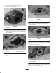
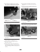
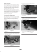
2. Loosen the screws securing each end of the front roller
to the height-of-cut arms (Fig. 1).
1
2
3
4
Figure 1
1. Roller mounting screws
2. Height-of-cut arm
3. Carriage bolt, washer &
locknut
4. Adjusting screw
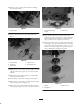
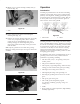
3. Remove the carriage bolts, washers and locknuts
securing the height-of-cut arms to each end of cutting
unit (Fig. 1). Remove the height-of-cut arms and roller
assembly.
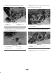
Note: Retain all parts for use if groomer is ever removed.
4. Remove the height-of-cut adjusting screws from the
height-of-cut arms (Fig. 1).