
Installation Instructions

1
All Rights Reserved
Printed in the USA
2003 by The Toro Company
8111 Lyndale Avenue South
Bloomington, MN 55420-1196
DPA Reel Mower Rear Roller Scraper Kit
Greensmaster 3000 Series
Model No. 04646
Form No. 3329–958 Rev. A
Installation Instructions
Note: The right and left side of the cutting unit is
determined from the rear of the unit.
1. Attach a bearing assembly to each end of the scraper
bar with 2 capscrews, washers and nuts (Fig. 1). Do
not tighten the nuts at this time.
2. Mount a scraper pin to the right cutting unit side plate
with a flatwasher and locknut (Fig. 1). Use the top
hole in the side plate and make sure the scraper pin
faces inward.
3. Slide the right hand spring onto the scraper pin
(Fig. 1). Position the spring as shown in figure 1.
4. Slide the right scraper bar bearing onto the scraper pin
(Fig. 1).
5. Slide the left hand spring onto the remaining scraper
pin (Fig. 1).
6. Insert the scraper pin into the bearing on the opposite
end of the scraper bar (Fig. 1).
7. Mount the scraper pin to the left cutting unit side plate
with a flatwasher and locknut (Fig. 1). Use the top
hole in the side plate.
Note: The small hook ends of the springs should be over
the cutting unit side plates. The large hook ends should be
over the scraper bar.
8. Slide the scraper bar bearing assemblies either upward
or downward in the slotted holes until the bottom of
the scraper bar is the same height at each end of the
top edge of the cutting unit bedknife or, the same as
the height of cut setting. Tighten the bearing mounting
fasteners to secure the adjustment.
9. Bend the scraper bar, if necessary, to ensure the bar is
flush with the full length of the roller and rests against
the roller with equal tension at all points.
Note: The proper height setting and tension of the scraper
against the roller is critical. The scraper bar will either not
properly clean the roller, will ruffle the grass or leave
large clumps of grass on the turf.
Important Spring the scraper bar away from the roller
and thoroughly wash the unit with a hose after each use.
Failure to follow this practice can result in pitting of the
roller.
10. Repeat procedure on remaining cutting units.
1
2
2
3
3
4
5
6
7
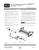
Figure 1
1. Scraper bar
2. Bearing assembly
3. Scraper pin
4. Spring (R.H.)
5. Spring (L.H.)
6. Small hook
7. Large hook