Form No. 3429-464 Rev A Universal Groomer Drive Kit Greensmaster® Flex™/eFlex® 1800 and 2100, or Greensmaster® 3000 Series DPA Cutting Units Model No. 04648—Serial No. 318000001 and Up Installation Instructions Introduction Read this information carefully to learn how to operate and maintain your product properly and to avoid injury and product damage. You are responsible for operating the product properly and safely. This product complies with all relevant European directives.
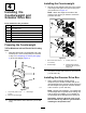
Loose Parts Use the chart below to verify that all parts have been shipped. Procedure 1 2 3 Description Qty. Use No parts required – Prepare the machine. No parts required – Prepare the cutting unit. No parts required – Remove the drive-belt assembly. 4 Weight Torx-socket screw Locknut Right reel adapter (silver) Left reel adapter (black) Shim washer Groomer drive box 1 2 2 1 1 1 1 Install the groomer drive box and weight.
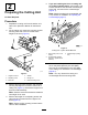
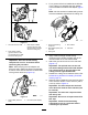
5. 2 Preparing the Cutting Unit If you are installing the kit on a cutting unit of a TriFlex hybrid machine, remove the 2 cap screws that secure the electrical counterweight to the reel, and remove the counterweight (Figure 3). Note: Retain the electrical counterweight and 2 cap screws for installation in Preparing the Counterweight (page 6). No Parts Required Procedure 1. Separate the cutting unit from the traction unit; refer to the Operator's Manual for the traction unit. 2.
g016226 Figure 5 1. Bolts g037843 Figure 4 1. Bolt (5/16 x 2-1/4 inches) 3. Bearing nut 2. Counterweight (reel-cutting unit) 7. Restrain the reel to remove the bearing nut; refer to Restraining the Reel for Removing Threaded Inserts (page 18). 8. Remove the bearing nut from the reel shaft (Figure 4). Important: Clean the threads in the end of the reel shaft of any debris or grease before installing the kit splined insert and groomer box. 9.
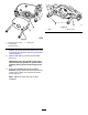
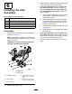
3 Removing the Belt-Drive Assembly Walk-Behind Greensmowers No Parts Required g017633 Figure 7 Procedure 1. Lower pulley 2. Set screws Note: Retain all parts in this section except where noted. 1. 4. Loosen the captive bolt securing the belt cover to the cutting unit until you can remove the cover (Figure 6). Remove the 3 bolts securing the belt-drive assembly to the cutting unit, if equipped, and remove the whole assembly (Figure 8). g017662 Figure 6 g037772 1. Belt-cover bolt (captive) 3.
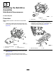
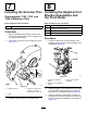
Installing the Counterweight 4 1. Installing the Counterweight and Groomer Drive Box Secure the new weight to the side of the cutting unit using 2 bolts (5/16 inch) and 2 nuts (5/16 inch) as shown in Figure 10. Note: Attach the weight to the side of the cutting unit on which you intend to mount the groomer drive box.
2. For a groomer drive box installed at the left side of the cutting unit, assemble the shim washer over the threads of the black reel adapter (Figure 13). Note: No shim washer is installed with groomer drive box installed at right side of the cutting unit. g232600 g037773 Figure 13 Figure 11 1. Groomer drive-box shaft 3. Reel adapter—black (groomer drive-box and counterweight at the left side of the cutting unit) 2.
Note: Do not damage the seal under the outer 5 cover. Note: The clutch-knob assembly comes installed from the factory for a right drive installation. 7. Installing the Groomer Drive Cap If you are installing the groomer at the left side of the machine, perform the following (Figure 14): A. Remove the O-ring from the clutch knob. B. Remove the shear pin that secures the clutch knob to the actuator shaft. Parts needed for this procedure: 1 C. Remove the clutch-knob assembly and flip it over. D.
6 3. Position the idler assembly on the opposite side of the reel from the groomer drive box. 4. If you are installing the kit on a cutting unit of a TriFlex machine, proceed to step 5. If you are installing the kit on the cutting unit of a walk-behind greensmower, perform the following steps: Installing the Idler Assembly A. Install the belt-drive assembly to the cutting unit using the 3 bolts that you removed previously (Figure 8). B.
7 8 Installing the Groomer Pins Installing the Height-of-Cut Bracket Assemblies and Greensmaster 3120, 3150, and the Front Roller 3250-D Machines Only Parts needed for this procedure: Parts needed for this procedure: 2 Groomer pin Procedure 1. 2. Apply removable thread-locking compound to the hole for the groomer pin if it is not present on the groomer-pin threads.
Note: Make sure that you bend the legs of the cotter pin so that the pin does not fall out of the adjuster pin. g031457 Figure 20 g033273 1. Cotter pin Figure 19 1. Cotter pin 2. Groomer drive box 3. Adjuster-arm assembly rod 4. Adjuster pin 2. Adjuster collar 5. 4. Align the adjuster-arm assembly rod near the idler assembly with the adjuster collar on the idler assembly and secure it with an adjuster pin and cotter pin (Figure 20). 3. Adjuster-arm assembly rod 4.
• 21-inch twin tip groomer blade (Model the height-of-groom springs at a low height of groom. When using this optional part, set the spring length to 19 mm (3/4 inch) when the groomer is in the engaged position (Figure 22). number 04802) • 21-inch soft grooming brush (Model number 04270) • 21-inch stiff grooming brush (Model number 04271) 2. Line up the groomer with the groomer drive box and idler assembly (Figure 23). g280237 Figure 22 1.
10 Install the Suspension Front Roller Parts needed for this procedure: – Pull link kit and extension coupler for Greensmaster 3120, 3150, and 3250 machines (ordered separately) Procedure Some machines require a pull link kit and extension couplers (Figure 24) when installing this universal groomer kit; refer to the following list and their installation instructions.
Operation • The type of grass on the green • The overall greens management program (i.e., irrigation, fertilizing, spraying, coring, overseeding, etc.) Introduction • Traffic Grooming is performed in the turf canopy above the soil level. Grooming promotes vertical growth of grass plants, reduces grain, and severs stolons, producing a denser turf. Grooming produces a more uniform and tighter playing surface for faster and truer action of the golf ball. • Stress periods (i.e.
Adjusting the Groomer Height Use the following chart, figures, and procedure to set the groomer height/depth. Number of rear-roller spacers required Height of cut (HOC) Height-of-grooming range (HOG) 0 1.5 mm (0.06 inch) 0.8 to 1.5 mm (0.03 to 0.06 inch) 3.0 mm (0.12 inch) 1.5 to 3.0 mm (0.06 to 0.12 inch) 4.8 mm (0.19 inch) 2.3 to 4.8 mm (0.09 to 0.19 inch) 6.4 mm (0.25 inch) 3.0 to 6.4 mm (0.12 to 0.25 inch) 7.9 mm (0.31 inch) 3.8 to 7.9 mm (0.15 to 0.31 inch) 9.7 mm (0.38 inch) 4.6 to 9.
Changing the Groomer Operating Direction Note: Adjust the grooming brush (up or down) in 0.25 mm (0.01 inch) increments to avoid unintended turf damage. 4. The groomer has 3 settings: NEUTRAL, FORWARD , and REVERSE. To change the direction of the groomer, turn the knob at the end of the groomer drive box and align the desired position with the adjustment notch. Make a pass over the test green, then lower the grooming reel 1/2 the roller level and make another pass over the test green.
Maintenance 8. Use a syringe (Part No. 137-0872) to fill the drive box with 50 cc of 80-90W oil. Changing the Gearbox Lubricant Service Interval After the first 100 hours Every 500 hours / Yearly (Whichever comes first) 1. 2. 3. 4. 5. Clean the external surfaces of the groomer housing. Important: Ensure that there is no dirt or clippings on the outside of the groomer housing; if debris gets inside of the groomer it can damage the gearbox.
Restraining the Reel Cleaning the Grooming Reel WARNING Service Interval: After each use The cutting reel blades are sharp and capable of amputating hands and feet. Clean off the grooming reel after using it by spraying it with water. Do not direct the water stream directly at the groomer bearing seals. Do not permit the grooming reel to stand in water so that the components rust. • Keep your hands and feet outside of the reel. • Ensure that the reel is restrained before servicing it.
Restraining the Reel for Installing Threaded Inserts 1. Insert a long-handled pry bar (recommended 3/8" x 12" with screwdriver handle) through the front of the cutting reel, closest to the side of the cutting unit that you will be torquing (Figure 33). 2. Place the pry bar against the weld side of the reel support plate (Figure 33). Note: Insert the pry bar between the top of the reel shaft and the backs of the reel blades so that the reel will not move.
Notes:
Notes:
Declaration of Incorporation The Toro Company, 8111 Lyndale Ave. South, Bloomington, MN, USA declares that the following unit(s) conform(s) to the directives listed, when installed in accordance with the accompanying instructions onto certain Toro models as indicated on the relevant Declarations of Conformity. Model No. 04648 Serial No.
EEA/UK Privacy Notice Toro’s Use of Your Personal Information The Toro Company (“Toro”) respects your privacy. When you purchase our products, we may collect certain personal information about you, either directly from you or through your local Toro company or dealer.
The Toro Warranty Two-Year or 1,500 Hours Limited Warranty Conditions and Products Covered Parts The Toro Company and its affiliate, Toro Warranty Company, pursuant to an agreement between them, jointly warrant your Toro Commercial product (“Product”) to be free from defects in materials or workmanship for 2 years or 1,500 operational hours*, whichever occurs first. This warranty is applicable to all products with the exception of Aerators (refer to separate warranty statements for these products).