Form No. 3443-656 Rev B Universal Groomer Drive Kit Greensmaster® Flex™/eFlex® 1800 and 2100, or Greensmaster® 3000 Series Compatible DPA Cutting Units Model No. 04648—Serial No.
Loose Parts Use the chart below to verify that all parts have been shipped. Procedure 1 2 3 4 Description Qty. Use No parts required – Prepare the machine. Torque wrench (Not included) – Gather the tools required for setup. No parts required – Prepare the cutting unit. No parts required – Remove the drive-belt assembly.
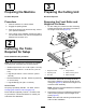
1 3 Preparing the Machine Preparing the Cutting Unit No Parts Required No Parts Required Procedure Removing the Front Roller and Height-of-Cut Arms 1. Park the machine on a level surface. 2. Engage the parking brake. 3. Shut off the engine and remove the key; refer to your Operator’s Manual. 4. If the cutting unit is installed, remove the cutting unit from the traction unit; refer to the Operator's Manual for the traction unit. 1.
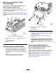
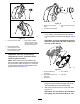
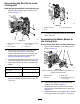
Removing the Electric Motor Counterweight Greensmaster 3000 Series Machines with Electric Reel-Drive Motors Only Remove the 2 cap screws that secure the electrical counterweight to the reel, and remove the counterweight (Figure 3). Note: Retain the electrical counterweight and 2 cap screws for assembly in Preparing the Counterweight (page 6). g037843 Figure 4 1. Bolt (5/16 x 2-1/4 inches) 3. Bearing nut 2. Counterweight (reel-cutting unit) 2.
g329966 Figure 5 1. Socket-head screw (5/16 x 1-1/4 inches) 3. Side plate g329654 Figure 6 2. Motor mount 1. Reel-drive housing 3. Socket-head screws 2. Cover 4 2. Removing the Reel-Drive Remove the flange-head screw (1/4 x 3/4 inch) that secures the reel-drive assembly to the side plate of the cutting unit (Figure 7). Walk-Behind Greensmowers Only No Parts Required Procedure Note: Retain all parts in this section except where noted. 1.
Installing the Counterweight 5 1. Installing the Counterweight and Groomer Drive Box Secure the new weight to the side of the cutting unit using 2 bolts (5/16 inch) and 2 nuts (5/16 inch) as shown in Figure 9. Note: Attach the weight to the side of the cutting unit on which you intend to mount the groomer drive box.
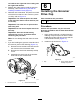
g350306 Figure 11 1. Wrench flats (drive-box shaft) 3. Groomer drive-box socket tool 2. Hex socket (reel adapter) 2. g349445 Figure 10 1. Groomer drive-box shaft For a groomer drive box installed at the left side of the cutting unit, assemble 2 shim washers over the threads of the black reel adapter (Figure 12). Important: If you are installing the groomer drive box at the right side of the cutting unit, use only 1 shim washer. 3.
reel shaft on the right side of the cutting unit has right-hand threads. 5. Restrain the cutting reel to install the gear box assembly; refer to Restraining the Reel for Installing Threaded Inserts (page 22). 6. While the reel is restrained, torque the hex-head of the drive-box shaft to 135 to 150 N∙m (100 to 110 ft-lb); refer to Figure 12.
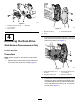
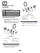
7 Installing the Idler Assembly Parts needed for this procedure: 1 Stub-shaft assembly 2 Bearing shield 1 Idler assembly 1 Adjuster collar 1 Flange nut g329967 Figure 16 Right side installation shown Assembling the Idler Plate 1. Assemble the stub-shaft assembly, 2 bearing shields, and flange nut to the idler assembly as shown in Figure 15. the fabric side toward the bearing in the idler. g329955 Figure 15 Left side installation shown 4.
Assembling the Reel Drive to the Cutting Unit Walk-Behind Greensmower Cutting Units Only 1. Align the idler assembly to the cutting unit as shown in Figure 17. g335505 Figure 18 1. Reel-drive housing 3. Socket-head screws 2. Cover 6. Assembling the Motor Mount to the Cutting Unit g335504 Figure 17 1. Flange-head screw (1/4 x 3/4 inch) 3. Socket-head screw (5/16 x 1-1/2 inches) 2. Idler assembly 4. Reel-drive 2.
that you removed in Removing the Motor Mount (page 4). 5. Torque the socket-head screws to 20 to 26 N∙m (175 to 225 in-lb). 8 Installing the Grass Basket Guards Greensmaster 3000 Series Cutting Units Only Parts needed for this procedure: 1 Grass basket guard (left) 1 Grass basket guard (right) 2 Flange-head screws g349743 Figure 20 Right side shown 1. Height-of-cut arm 3. Grass basket guard (right) 2. Hole 4.
g349744 Figure 21 1. Height-of-cut adjusting screw g349746 Figure 22 3. Height-of-cut bracket assembly 2. Plow bolt and flange locknut 1. Hardened washer 2. Adjuster-arm assembly rod 2. Install the height-of-cut assemblies to the cutting unit side plates using the previously removed plow bolt, nut, and special washer (Figure 21). 5. 3. Apply medium-strength thread-locking compound (such as Blue Loctite® 243) to the shoulder bolts before installing them to the adjuster-arm assemblies. 4.
6. Insert and center the front roller shaft between the height-of-cut brackets and secure it with the 2 mounting screws removed from the old height-of-cut brackets (Figure 24). 2. Line up the grooming reel assembly with the groomer drive box and idler assembly (Figure 25). g231793 Figure 24 1. Mounting screw 3. Groomer guard 2. Height-of-cut bracket assembly 7. Attach the groomer guards to either side of the front roller shaft (Figure 24). 8.
5. 11 Adjusting the Groomer Spring Force 12 Parts needed for this procedure: – Install the Suspension Front Roller Washer (Part No. 3256-24, not included) Procedure For low height-of-groom setups where additional spring force is required, install additional washers (Part No. 3256-24) to the eye bolt to compress the height-of-groom springs at a low height of groom. 1. Subtract the desired (.75 inch or 19 mm) spring length from the current spring length, and divide this difference by 0.
Operation • The type of grass on the green • The overall greens management program (i.e., irrigation, fertilizing, spraying, coring, overseeding, etc.) Introduction • Traffic Grooming is performed in the turf canopy above the soil level. Grooming promotes vertical growth of grass plants, reduces grain, and severs stolons, producing a denser turf. Grooming produces a more uniform and tighter playing surface for faster and truer action of the golf ball. • Stress periods (i.e.
Adjusting the Groomer Height Note: If you are using the groomer on an eFlex traction unit, note that the groomer causes the traction unit to deplete the battery faster than when not running the groomer. The deeper into the grass you set the groomer, the more power it requires and the faster the machine uses up the battery charge. Use the following chart, figures, and procedures to set the groomer height/depth.
Changing the Groomer Operating Direction The groomer has 3 settings: NEUTRAL (N), FORWARD (F), and REVERSE (R). To change the direction of the groomer, turn the knob at the end of the groomer drive box and align the desired position with the adjustment notch. g031469 Figure 28 1. Height-adjuster knob 3. Groomer height (HOG) 2. Quick-up lever (shown in the ENGAGED position) 4. Number of rear-roller spacers (below side plate pad) 3. 4.
Transporting the Machine Note: Adjust the grooming brush (up or down) in 0.25 mm (0.01 inch) increments to avoid unintended turf damage. 4. When you wish to mow without the groomer or need to transport the machine, move the quick-up lever to the TRANSPORT position (Figure 30). Make a pass over the test green, then lower the grooming reel 1/2 the roller level and make another pass over the test green. Note: This moves the groomer reel into a raised position. Note: For example, to set a 3.
Maintenance 7. Install the drain plug. 8. Use a syringe (Part No. 137-0872) to fill the drive box with 50 cc of 80-90W oil. Changing the Gearbox Lubricant Service Interval After the first 100 hours Every 500 hours / Yearly (Whichever comes first) 1. Clean the external surfaces of the groomer housing. Important: Ensure that there is no dirt or clippings on the outside of the groomer housing; if debris gets inside of the groomer it can damage the gearbox. g349498 Figure 32 2.
Removing the Groomer Drive Box turn the groomer drive hex-head clockwise (left-hand thread) to remove drive-box shaft from cutting unit Note: Retain all removed parts for later installation unless otherwise stated. Important: You must use a 6-point socket with heavy wall. Important: If you have any issues removing the groomer drive box, refer to your traction unit Service Manual or contact your authorized Toro distributor. 1. Remove the cap from the groomer. 2.
This is especially important in sandy soil and/or when the groomer is set for penetration. Restraining the Reel WARNING The cutting reel blades are sharp and capable of amputating hands and feet. • Keep your hands and feet outside of the reel. • Ensure that the reel is restrained before servicing it. Restraining the Reel for Removing Threaded Inserts 1. 2. 3. Tip up the cutting unit so that you access the bottom of the reel.
Restraining the Reel for Installing Threaded Inserts 1. Insert a long-handled pry bar (recommended 3/8 x 12 inches with a screwdriver handle) through the front of the cutting reel, closest to the side of the cutting unit that you will be torquing (Figure 37). 2. Place the pry bar against the weld side of the reel support plate (Figure 37). Note: Insert the pry bar between the top of the reel shaft and the backs of the reel blades so that the reel will not move.
Notes:
Notes:
Declaration of Incorporation The Toro Company, 8111 Lyndale Ave. South, Bloomington, MN, USA declares that the following unit(s) conform(s) to the directives listed, when installed in accordance with the accompanying instructions onto certain Toro models as indicated on the relevant Declarations of Conformity. Model No. 04648 Serial No.
EEA/UK Privacy Notice Toro’s Use of Your Personal Information The Toro Company (“Toro”) respects your privacy. When you purchase our products, we may collect certain personal information about you, either directly from you or through your local Toro company or dealer.
The Toro Warranty Two-Year or 1,500 Hours Limited Warranty Parts Conditions and Products Covered The Toro Company warrants your Toro Commercial product (“Product”) to be free from defects in materials or workmanship for 2 years or 1,500 operational hours*, whichever occurs first. This warranty is applicable to all products with the exception of Aerators (refer to separate warranty statements for these products).