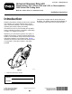
Form No. 3442-442 Rev A Universal Groomer Drive Kit Greensmaster® Flex™/eFlex® 1800 and 2100, or Greensmaster® 3000 Series DPA Cutting Units Model No. 04648—Serial No. 319003270 and Up Installation Instructions Introduction Read this information carefully to learn how to operate and maintain your product properly and to avoid injury and product damage. You are responsible for operating the product properly and safely. This product complies with all relevant European directives.
Loose Parts Use the chart below to verify that all parts have been shipped. Procedure 1 2 3 Description Qty. Use No parts required – Prepare the machine. No parts required – Prepare the cutting unit. No parts required – Remove the drive-belt assembly. 4 Weight Torx-socket screw Locknut Right reel adapter (silver) Left reel adapter (black) Shim washer Groomer drive box 1 2 2 1 1 2 1 Install the groomer drive box and weight.
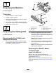
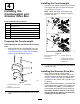
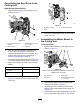
1 Preparing the Machine No Parts Required Procedure 1. Park the machine on a level surface. 2. Engage the parking brake. 3. Shut off the motor and remove the key; refer to your Operator’s Manual. 4. If the cutting unit is installed, remove the cutting unit from the traction unit; refer to the Operator's Manual for the traction unit. g335501 Figure 2 2 Preparing the Cutting Unit 1. Height-of-cut arm 4. Flange locknut 2. Adjusting screw 5. Roller-mounting screw 3. Plow bolt 6.
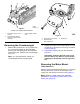
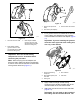
g037842 Figure 3 Cutting Unit—Hybrid TriFlex Machine 1. Cap screws (5/16 x 2-3/4 inches) 3. Counterweight (cutting unit) g037843 Figure 4 2. Counterweight (electric reel drive—hybrid TriFlex machine) 1. Bolt (5/16 x 2-1/4 inches) 2. Counterweight (reel-cutting unit) Removing the Counterweight 1. 3. Bearing nut Remove the 2 bolts (5/16 x 2-1/4 inches) from the 2 nuts (held captive by the side plate) securing the counterweight on the side plate of the cutting unit.
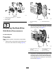
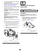
g329966 Figure 5 1. Socket-head screw (5/16 x 1-1/4 inches) 3. Side plate g329654 Figure 6 2. Motor mount 1. Reel-drive housing 3. Socket-head screws 2. Cover 3 2. Removing the Reel-Drive Remove the flange-head screw (1/4 x 3/4 inch) that secures the reel-drive assembly to the side plate of the cutting unit (Figure 7). Walk-Behind Greensmowers No Parts Required Procedure Note: Retain all parts in this section except where noted. 1.
Installing the Counterweight 4 1. Installing the Counterweight and Groomer Drive Box Secure the new weight to the side of the cutting unit using 2 bolts (5/16 inch) and 2 nuts (5/16 inch) as shown in Figure 9. Note: Attach the weight to the side of the cutting unit on which you intend to mount the groomer drive box.
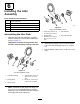
g335523 Figure 11 1. Wrench flats (drive-box shaft) 3. Groomer drive-box wrench 2. Hex socket (reel adapter) 2. g335503 Figure 10 1. Groomer drive-box shaft For a groomer drive box installed at the left side of the cutting unit, assemble 2 shim washers over the threads of the black reel adapter (Figure 12). Important: If you are installing the groomer drive box at the right side of the cutting unit, use only 1 shim washer. 3.
reel shaft on the right side of the cutting unit has right-hand threads. 5. Restrain the cutting reel to install the gear box assembly; refer to Restraining the Reel for Installing Threaded Inserts (page 21). 6. While the reel is restrained, torque the hex-head of the drive-box shaft to 135 to 150 N∙m (100 to 110 ft-lb); refer to Figure 12.
6 Installing the Idler Assembly Parts needed for this procedure: 1 Stub-shaft assembly 2 Bearing shield 1 Idler assembly 1 Adjuster collar 1 Flange nut g329967 Figure 16 Right side installation shown Assembling the Idler Plate 1. Assemble the stub-shaft assembly, 2 bearing shields, and flange nut to the idler assembly as shown in Figure 15. the fabric side toward the bearing in the idler. g329955 Figure 15 Left side installation shown 4.
Assembling the Reel Drive to the Cutting Unit Walk-Behind Greens Mowers 1. Align the idler assembly to the cutting unit as shown in Figure 17. g335505 Figure 18 1. Reel-drive housing 3. Socket-head screws 2. Cover 6. Assembling the Motor Mount to the Cutting Unit g335504 Figure 17 1. Flange-head screw (1/4 x 3/4 inch) 3. Socket-head screw (5/16 x 1-1/2 inches) 2. Idler assembly 4. Reel-drive 2.
that you removed in Removing the Motor Mount (page 4). Torque the socket-head screws to 20 to 26 N∙m (175 to 225 in-lb). 5. 3. Perform this procedure to the opposite side. 8 7 Installing the Height-of-Cut Bracket Assemblies and Installing the Groomer Pins the Front Roller Greensmaster 3120, 3150, and 3250-D Machines Only Parts needed for this procedure: Parts needed for this procedure: 2 Groomer pin Procedure 1. 2.
Note: Make sure that you bend the legs of the cotter pin so that the pin does not fall out of the adjuster pin. g031457 Figure 23 g033273 1. Cotter pin Figure 22 1. Cotter pin 2. Groomer drive box 3. Adjuster-arm assembly rod 4. Adjuster pin 2. Adjuster collar 5. 4. Align the adjuster-arm assembly rod near the idler assembly with the adjuster collar on the idler assembly and secure it with an adjuster pin and cotter pin (Figure 23). 3. Adjuster-arm assembly rod 4.
2. the height-of-groom springs at a low height of groom. When using this optional part, set the spring length to 19 mm (3/4 inch) when the groomer is in the engaged position (Figure 25). Line up the grooming reel assembly with the groomer drive box and idler assembly (Figure 26). g280237 Figure 25 1. Set the spring length to 19 mm (3/4 inch) in the engaged position. 2. Optional flange nut (Part No. 3290-357) g283516 Figure 26 1. Drive-stub shaft 4. Shaft clamp (4) 2. Jam locknut (4) 5.
Operation 10 Introduction Install the Suspension Front Roller Grooming is performed in the turf canopy above the soil level. Grooming promotes vertical growth of grass plants, reduces grain, and severs stolons, producing a denser turf. Grooming produces a more uniform and tighter playing surface for faster and truer action of the golf ball.
• The overall greens management program (i.e., irrigation, fertilizing, spraying, coring, overseeding, etc.) • Traffic • Stress periods (i.e., hot temperatures, high humidity, unusually high traffic) These factors can vary from green to green. Inspect the greens frequently and change the grooming practice as needed. Various grooming shaft assemblies are available. The 13 mm (1/2 inch) spacing allows you to groom slightly deeper to cut stolons without thinning out the turf excessively.
Adjusting the Groomer Height Note: If you are using the groomer on an eFlex traction unit, note that the groomer causes the traction unit to deplete the battery faster than when not running the groomer. The deeper into the grass you set the groomer, the more power it requires and the faster the machine uses up the battery charge. Use the following chart, figures, and procedures to set the groomer height/depth.
the height-adjuster knob (Figure 28) to raise or lower the tip of the groomer blade to the desired height. 4. DANGER Contact with the reels or other moving parts can result in personal injury. • Before you make any adjustments to the cutting unit, disengage the cutting unit, engage the parking brake, shut off the engine, and wait for all movement to stop. • Keep your hands, feet, and clothing away from the reel or other moving parts.
Maintenance After testing the performance of the groomer on a test green and you obtain satisfactory results, you can begin grooming on the playing greens. However, each green may respond differently to grooming. In addition, growing conditions constantly change. Inspect the groomed greens frequently and adjust to the grooming procedure as often as necessary.
7. Install the drain plug. 8. Use a syringe (Part No. 137-0872) to fill the drive box with 50 cc of 80-90W oil. Cleaning the Grooming Reel Service Interval: After each use Clean off the grooming reel after using it by spraying it with water. Do not direct the water stream directly at the groomer bearing seals. Do not permit the grooming reel to stand in water so that the components rust.
Restraining the Reel WARNING The cutting reel blades are sharp and capable of amputating hands and feet. • Keep your hands and feet outside of the reel. • Ensure that the reel is restrained before servicing it. Restraining the Reel for Removing Threaded Inserts 1. Tip up the cutting unit so that you access the bottom of the reel. 2.
Restraining the Reel for Installing Threaded Inserts 1. Insert a long-handled pry bar (recommended 3/8 x 12 inches with a screwdriver handle) through the front of the cutting reel, closest to the side of the cutting unit that you will be torquing (Figure 35). 2. Place the pry bar against the weld side of the reel support plate (Figure 35). Note: Insert the pry bar between the top of the reel shaft and the backs of the reel blades so that the reel will not move.
Declaration of Incorporation The Toro Company, 8111 Lyndale Ave. South, Bloomington, MN, USA declares that the following unit(s) conform(s) to the directives listed, when installed in accordance with the accompanying instructions onto certain Toro models as indicated on the relevant Declarations of Conformity. Model No. 04648 Serial No.
EEA/UK Privacy Notice Toro’s Use of Your Personal Information The Toro Company (“Toro”) respects your privacy. When you purchase our products, we may collect certain personal information about you, either directly from you or through your local Toro company or dealer.
The Toro Warranty Two-Year or 1,500 Hours Limited Warranty Conditions and Products Covered Parts The Toro Company and its affiliate, Toro Warranty Company, pursuant to an agreement between them, jointly warrant your Toro Commercial product (“Product”) to be free from defects in materials or workmanship for 2 years or 1,500 operational hours*, whichever occurs first. This warranty is applicable to all products with the exception of Aerators (refer to separate warranty statements for these products).