
Installation Instructions
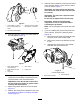


6.Removethecapandtoexposethebearingnut
(Figure3).
7.Removethebearingnutfromthereelshaft
(Figure3).
Important:Cleanthethreadsintheendof
thereelshaftofanydebrisorgreasebefore
installingthesplinedinsertandgroomerbox
fromthiskit.
3
RemovingtheReel-Drive
Assembly
NoPartsRequired
Procedure
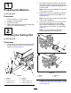
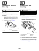
1.Removethehardwarethatsecuresthereel-drive
assemblytothesideplate(Figure4).
g287976
Figure4
1.Socket-headscrew4.Springwasher
2.Spacer5.O-ring
3.Washer6.Nut
2.Removethereel-driveassembly,atwashers,
springwashers,spacers,andO-ringsfromthe
sideplate(Figure4).
4
InstallingtheGroomer
DriveBox
Partsneededforthisprocedure:
1Reeladapter
1
Shimwasher
1
Groomerdrivebox
Procedure
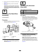
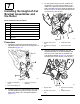
1.Applymedium-strength,thread-locking
compound(suchasBlueLoctite®243)tothe
internalthreadsofthedrive-boxshaftandtorque
thereeladapterandgroomerdrive-boxshaftto
150to163N∙m(110to120ft-lb).
g283538
Figure5
1.Groomerdrive-boxshaft
2.Reeladapter
Important:Allowthethread-locking
compoundtocurefor15minutesbefore
continuingtheprocedure.
Note:Whentorquingthereeladapterand
drive-boxshaft,restrainthedrive-boxshaftwith
thegroomerdrive-boxsockettoolora1-3/8
inchwrenchandlockedinaviceonthewrench
atsattheinboardsideofthegroomerdrivebox
(Figure6).
4