
Installation Instructions

5
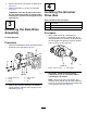
InstallingtheGroomer
DriveCap
Partsneededforthisprocedure:
1
Cap
Procedure
PerformthisprocedureonlyforUniversal
GroomerassemblieswithnoRearRollerBrush
Kitinstalled:
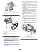
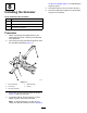
1.Applymedium-strength,cylindrical-bonding
retainingcompound(suchasGreenLoctite
609®)aroundthesnapringgrooveandthe
outerdiametersurface(Figure9).
2.InstallthecapasshowninFigure9.
g299664
Figure9
1.Cap
2.Applymedium-strength
bondingcompound
6
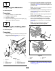
InstallingtheIdler
Assembly
Partsneededforthisprocedure:
1
Stub-shaftassembly
2Bearingshield
1Idlerassembly
1Adjusterpin
1
Cotterpin
1Flangenut
Procedure
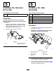
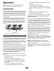
1.Assembletheloosepartstotheidlerassembly
asshowninFigure10.
Important:Installthebearingshieldswith
thefabricsidetowardthebearings.
g281674
Figure10
1.Stub-shaftassembly
5.Adjusterpin
2.Bearingshield6.Flangenut
3.Idlerassembly7.Bearingshield
4.Cotterpin
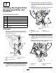
2.Positiontheidlerassemblyontheoppositeside
ofthereelfromthegroomerdrivebox.
3.Usethepreviouslyremovedhardwaretoinstall
thereel-driveassembly;referto3Removingthe
Reel-DriveAssembly(page4).
6