
Installation Instructions
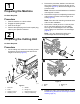
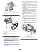
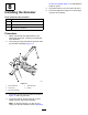

5.Insertandcentertherollershaftbetweenthe
height-of-cut(HOC)bracketsandsecureitwith
2mountingscrews(Figure14orFigure15).
Youcaninstallthemountingscrewsinthefront
(asshowninFigure14)orrearside(Figure15)
oftheHOCbrackets.Installingthescrewsin
thefrontsidewillallowthegroomertoclearthe
roller;installingthemintherearsidewillallow
thegroomertointerlacewiththeroller.
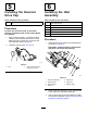
g287988
Figure14
MountingscrewsinstalledtofrontsideofHOCbrackets
1.Roller
3.Height-of-cutbracket
(HOC)assembly
2.Mountingscrew
4.Groomerguard
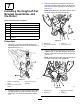
g287989
Figure15
MountingscrewsinstalledtorearsideofHOCbrackets
1.Groomerguard3.Height-of-cutbracket
(HOC)assembly
2.Mountingscrew4.Roller
6.Attachthegroomerguardstobothsidesofthe
rollershaft(Figure14).
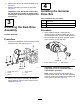
7.Torquethegroomerguardsto22to24N∙m(16
to18ft-lb).
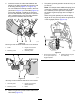
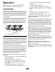
Note:Forsetupswhereadditionalspringforce
isrequired,installtheoptionalangenut(Part
No.3290-357)totheeyebolttocompress
theheight-of-groomspringsatalowheightof
groom.
Whenusingthisoptionalpart,setthespring
lengthto19mm(3/4inch)whenthegroomeris
intheengagedposition(Figure16).
g283296
Figure16
1.Setthespringlengthto
19mm(3/4inch)inthe
engagedposition.
2.Optionalangenut(Part
No.3290-357)
8