
Operator's Manual
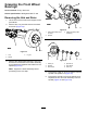

InstallingtheHubandRotor
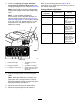
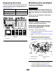
1.Applyalightcoatofthespeciedgreasetothe
spindle(Figure37).
g192344
Figure37
1.Nutretainer
4.Outerbearing
2.Spindlenut
5.Hub,rotor,innerbearing,
race,andseal
3.Tabwasher
6.Spindle
2.Assemblethehubandrotorontothespindle
withtherotorinboard(Figure37).
3.Assembletheoutboardbearingontothespindle
andseatthebearingtotheoutboardrace
(Figure37).
4.Assemblethetabwasherontothespindle
(Figure37).
5.Threadthespindlenutontothespindleand
tightenthenutto15N∙m(11ft-lb),whilerotating
thehubtoseatthebearing(Figure37).
6.Loosenthespindlenutuntilthehubrotates
freely.
7.Torquethespindlenutto170to225N∙cm(15
to20in-lb).
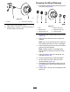
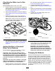
8.Installtheretaineroverthenutandcheckthe
alignmentoftheslotintheretainerandthehole
inthespindleforthecotterpin(Figure38).
Note:Iftheslotintheretainerandtheholein
thespindlearenotaligned,tightenthespindle
nuttoaligntheslotandholetoamaximum
torqueof226N∙cm(20in-lb)onthenut.
g192345
Figure38
1.Cotterpin
3.Dustcap
2.Nutretainer
9.Installthecotterpinandbendeachlegsaround
theretainer(Figure38).
10.Installthedustcapontothehub(Figure38).
11.Repeatsteps1through10forthehubandrotor
attheothersideofthemachine.
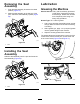
InstallingtheBrakesandWheels
1.Cleanthe2ange-headbolts(3/8x3/4inch)
andapplyacoatofanti-seizecompoundtothe
threadsofthebolts.
2.Alignthebrakepadstoeithersideoftherotor
(Figure33)andtheholesinthecaliperbracket
withtheholesinthebrakemountofthespindle
frame(Figure37).
3.Assemblethecaliperbrackettothespindle
frame(Figure33)withthe2ange-headbolts
(3/8x3/4inch),andtorquetheboltsto47to54
N∙m(35to40ft-lb).
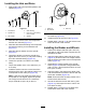
4.Aligntheholesinthewheeltothestudsofthe
hubandassemblethewheeltothehubwiththe
valvestemoutward(Figure32).
Note:Ensurethatthemountingsurfaceofthe
wheelisushwiththehub.
5.Securethewheeltothehubwiththelugnuts
(Figure32),andtorquethenutsto108to122
N∙m(80to90ft-lb).
6.Repeatsteps1through5forthebrakeand
wheelattheothersideofthemachine.
34