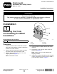
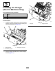
Form No. 3413-135 Rev B Finishing Kit Workman® GTX Utility Vehicle Model No. 07045 Installation Instructions WARNING CALIFORNIA Proposition 65 Warning This product contains a chemical or chemicals known to the State of California to cause cancer, birth defects, or reproductive harm. Installation 1 Removing the Crate and Installing the Wheel Assemblies Parts needed for this procedure: 4 g190827 Figure 1 Wheel assembly 1. Hub 2. Lug nut Procedure 1.
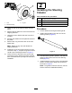
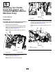
Installing the Steering Column Parts needed for this procedure: g190874 Figure 2 1. Hub 3. Lug nut 2. Wheel assembly 7. Lower the rear of the machine back onto the pallet. 8. Remove the two bolts from each of the front two shipping brackets. 9. Using the hoist or forklift, raise the front of the machine. 10. Roll the rear wheels off of the pallet and remove the pallet. 11. Remove the 4 lug nuts from each of the front wheel hubs.
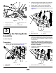
2. Rotate the dash bracket upward, and install the top bolt and tighten the bottom bolt (Figure 5). 3. Repeat steps 1 and 2 for the other bracket. 4. Remove the top bolt and nut and loosen the bottom bolt and nut on the parking-brake bracket (Figure 6). g198910 Figure 4 1. Flange nut (5/16 inch) 3. Carriage bolt (5/16 x 3/4 inch) 2. Steering column 4. Steering shaft 3 g191533 Figure 6 Installing the Parking-Brake Assembly 1. Top nut 3. Parking-brake bracket 2. Bottom bolt and nut 4.
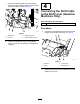
7. Secure the parking-brake link to the parking brake and cable-equalizer bracket using 2 clevis pins and 2 hairpin cotters (Figure 8). 4 Connecting the Shift Cable to the Shift Lever (Gasoline Machines Only) Parts needed for this procedure: 1 Spring Procedure 1. g191532 Figure 8 1. Hairpin cotter 3. Parking-brake link 2. Clevis pin 4. Cable-equalizer bracket 8. Connect the shift cable ball joint to the shift lever using the locknut (#10) as shown in Figure 9.
Installing the Charger (Electric Machines Only) Parts needed for this procedure: 1 Charger 1 Charger bracket 2 Thread-forming screw (5/16 x 3/4 inch) Procedure 1. g191363 Figure 11 Install the charger bracket to the left side battery support using the 2 thread-forming screws (5/16 x 3/4 inch) as shown in Figure 10. 1. Charger g191364 Figure 10 1. Charger bracket 3. Screw (5/16 x 3/4 inch) 2. Side battery support 2. Set the charger vertically on top of the charger bracket (Figure 11).
Removing the Throttle Pedal, Key Switch, and Converter Module (Electric Machines Only) g191369 Figure 13 No Parts Required 1. Key switch 2. Key Procedure 4. Important: Do not press the throttle pedal while it is secured with a bolt; it will break the ear. 1. Disconnect the wire harness. 2. Remove the bolt and nut securing the throttle pedal, and remove the throttle pedal from its temporary position (Figure 12).
. 7 Verify that the parking brake is adjusted to the proper tension by performing the following procedure: Setting the Parking-Brake Tension A. Engage the parking brake by pulling the parking-brake lever toward you, until you feel tension. B. If you do not feel tension when pulling the parking-brake toward you within 11.4 to 16.5 cm (4-1/2 to 6-1/2 inches) from the “P” symbol on the dash, then you need to adjust the parking brake. No Parts Required Procedure 1.
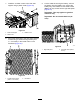
Procedure 9 1. Set the floorboard down onto the machine frame (Figure 17). Note: Ensure that you orient the floorboard as Installing the Seat Base shown in Figure 17.
3. Install the front seat support to the left and right vertical seat supports using the 2 bolt with washer assemblies (1/4 x 1/2 inch) as shown in Figure 19. 5. Install the left and right panel bracket the machine using the 2 bolts (1/4 x 2 inches), washer (1/4 inch), and locknut (1/4 inch) as shown in Figure 21. Note: Orient the hardware as shown in Figure 21. g191604 Figure 19 1. Vertical seat support g191597 3. Front seat support Figure 21 2. Bolt with washer assembly (1/4 x 1/2 inch) 4.
7. Install the 2 rubber covers to the rear seat support using 4 plastic rivets (Figure 23). 9. Cut the cable tie securing the battery, remove the battery from the battery tray, remove the battery tray, and install the 2 torx-head screws (M60 x 22 mm) screws into the right side panel (Figure 25). Important: This step applies to gasoline machines only. Important: Do not exceed 249 N∙cm (22 in-lb). g191669 Figure 23 1. Rear seat support 3. Rubber cover 2. Plastic rivet 8.
10. Secure the charger bracket to the left side panel using 4 torx-head screws (M60 x 22 mm) as shown in Figure 26. 11. Install the left side panel using 4 torx-head screws (M60 x 22 mm) as shown in Figure 27. Important: This step applies to electric machines only. Important: This step applies to electric machines only. Important: Do not exceed 249 N∙cm (22 Important: Do not exceed 249 N∙cm (22 in-lb). in-lb). g193101 Figure 26 1. Left side panel 3. Torx-head screw (M60 x 22 mm) 2.
. Repeat step 11 on the right side. 13. Set the charger horizontally into the charger bracket, and install the charger to the bracket using the 4 flange bolts (1/4 x 5/8 inch) and 4 flange nuts (5/8 inch) as shown in Figure 28. Important: This step applies to gasoline Important: This step applies to electric in-lb). 15. Install the 2 side panels using 6 torx-head screws (M60 x 22 mm) on each side (Figure 29). machines only. Important: Do not exceed 249 N∙cm (22 machines only.
17. Install the charger-function light cord and power cord into the charger bracket, and secure the power cord with the 2 phillips-head screws (#6 x 1/2 inch) and 2 locknuts (#6) as shown in Figure 32. Important: This step applies to electric machines only. g036760 Figure 30 Left Handhold Shown 1. Handhold (short) 3. Flange nut (5/16 inch) 2. Flange bolt (5/16 x 3/4 inch) g191366 Figure 32 g036761 Figure 31 Right Handhold Shown 1. Handhold (tall) 3. Flange nut (5/16 inch) 2.
2. 10 Install the footboard-to-dash bracket to the dash brackets using 3 thread-forming screws (1/4 x 3/4 inch) and a flange nut (1/4 inch) as shown in Figure 34.
g191697 Figure 36 1. Torx-head screw (1/4 x 1-1/4 inches) 2. Footboard to vertical frame g191699 Figure 38 5. Loosely install the outer dash brackets to the dash reinforcement using a thread-forming screw (1/4 x 3/4 inch) and flange nut (1/4 inch) on each side (Figure 37). 1. Thread-forming screw (1/4 x 3/4 inch) 3. Footboard-to-dash bracket 2. Outer dash bracket 7. Install the choke cable through the dash (Figure 39). Important: This step applies to gasoline machines only. g191698 Figure 37 1.
10. Install converter module to the dash reinforcement using 2 screws (#10 x 1/2 inch) and 2 flange nuts (#10) as shown in Figure 40. 13. Set the dash over the parking-brake lever. 14. Secure the dash using 10 torx-head screws (1/4 x 1-1/4 inches) as shown in Figure 42. Important: This step applies to electric machines only. Important: Install the screws from the center out, leaving the screws loose until all 10 are installed. Tighten the screws from the center out. g227497 Figure 40 g227500 1.
11 Installing the Throttle Pedal (Electric Machines Only) Parts needed for this procedure: 1 Throttle pedal 3 Bolt (5/16 x 1 inch) 3 Nut (5/16 inch) Procedure 1. Pull the connector for the throttle pedal though the dash and connect it to the pedal. 2. Install the throttle pedal using the 3 bolts (5/16 x 1 inch) and 3 nuts (5/16 inch) as shown in Figure 43. g191598 Figure 43 1. Bolt and nut (not shown) 2.
12 Installing the Wire Harness Parts needed for this procedure: 3 Self-tapping screw (#10 x 1/2 inch) 1 Horn button For Gasoline Machines 1. Cut the cable ties securing the wire harness. 2. Unplug the switches. 3. Route the wire harness as shown in Figure 44. g227498 Figure 44 Some Parts Hidden for Clarity 4. Install the hour meter, headlight switch, key switch, horn button, and USB power point into the dash (Figure 45 and Figure 46).
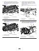
g227499 Figure 45 1. Gear-shift indicator 6. Parking-brake lever 2. Gear-shift lever 3. Horn button 7. Choke control 8. Brake pedal 4. Key switch 9. Accelerator pedal 5. USB power point g033954 Figure 46 1. Headlight switch 2. Hour meter 5. Install the wire harness to the hour meter, headlight switch, key switch, horn, horn button, and USB power point. 6. Install plugs into the remaining dash openings.
7. Install the 3 relays to the dash reinforcement using 3 self-tapping screws (#10 x 1/2 inch) as shown in Figure 47. g193166 Figure 47 3. Relay 1. Dash reinforcement 2. Self-tapping screw (#10 x 1/2 inch) 8. Install the wire harness to the accelerator-pedal switch (Figure 44). For Electric Machines 1. Cut the cable ties securing the wire harness. 2. Unplug the switches. 3. Route the wire harness as shown in Figure 48. g227501 Figure 48 Some Parts Hidden for Clarity 4.
g227502 Figure 49 1. Headlight switch 7. Parking-brake lever 2. Hour meter 8. Brake pedal 3. Battery-discharge indicator 9. Accelerator pedal 4. Horn button 10. USB power point 5. Gear-shift selector 11. Status-indicator light 6. Key switch 5. Install the wire harness to the headlight switch, battery-discharge indicator, gear-shift selector, status-indicator light, key switch, hour meter, horn, horn button, and USB power point. Note: Polarity is important on the USB power point.
Note: The fender should fit in between the footboard and the fender bracket. 13 Installing the Fenders Parts needed for this procedure: 1 Left fender 1 Right fender 2 Fender decal 4 Whiz bolt (1/4 x 5/8 inch) 6 Flat washer (5/16 inch) 4 Locknut (1/4 inch) 2 Angle bracket 6 Torx-head screw (1/4 x 1-1/4 inches) 6 g191714 Figure 51 Wheel Hidden for Clarity Hex-flange nut (1/4 inch) Procedure 1. 2. Apply the fender decal to the side of the fender (Figure 50).
5. Loosely install the fender to the top of the footboard using a torx-head screw (1/4 x 1-1/4 inches), a hex-flange nut (1/4 inch), and a flat washer (5/16 inch) as shown in Figure 53. g193194 Figure 54 Some Parts Hidden for Clarity 1. Cable tie g198839 Figure 53 Wheel Hidden for Clarity 1. Torx-head screw (1/4 x 1-1/4 inches) 3. Fender 2. Footboard 4. Hex-flange nut (1/4 inch) 6. Repeat this procedure for the other fender. 7. Tighten all of the hardware. 2. Choke cable 2.
15 16 Installing the Footboard Cover Installing the Fuel Tank (Gasoline Machines Only) Parts needed for this procedure: Parts needed for this procedure: 1 Footboard cover 1 Fuel tank 2 Plastite screw 1 Fuel-tank decal 2 Torx-head screw (1/4 x 1-1/4 inches) 1 Hold-down 1 Fuel line 1 Carriage bolt (5/16 x 3/4 inch) 2 Torx-head screw (M60 x 22 mm) Procedure Install the footboard cover using 2 plastite screws and 2 torx-head screws (1/4 x 1-1/4 inches) as shown in Figure 56.
Important: Do not exceed 249 N∙cm (22 in-lb). 5. Connect the fuel line from the fuel tank to the fuel pump (Figure 57). 6. Apply the fuel-tank decal above the fuel-tank cap onto the left side panel. 17 Installing the Battery (Gasoline Machines Only) Parts needed for this procedure: 1 Bolt (1/4 x 5-1/4 inches) 1 Battery-plate clamp 1 Battery-channel clamp 1 Flat washer (9/32 inch) 1 Locknut (1/4 inch) 2 Torx-head screw (M60 x 22 mm) Procedure 1.
18 19 Connecting the Battery (Gasoline Machines Only) Connecting the Batteries (Electric Machines Only) No Parts Required No Parts Required Procedure Procedure WARNING 1. Ensure that the battery terminals are clean and free of oxidation. Incorrect battery cable routing could damage the machine and cables, causing sparks. Sparks can cause the battery gasses to explode, resulting in personal injury. 2.
20 21 Checking and Adjusting the Shift Cable (Gasoline Machines Only) Installing the Hood Parts needed for this procedure: 1 Hood No Parts Required Procedure Procedure 1. 1. Set the gear-shift selector to the NEUTRAL position. Slide the hood pins into the slots on the bumper (Figure 62). Note: The tab on the headlight bracket locks the 2. Rotate the secondary clutch to see if it spins freely in the NEUTRAL position. 3. Set the gear-shift selector to the FORWARD position. 4.
22 23 Installing the Hitch Assembly Installing the Cargo Bed Latch Strikers Parts needed for this procedure: No Parts Required 1 Hitch assembly 1 Flange-head bolt (1/2 x 2-1/4 inches) 1 Locknut (1/2 inch) Procedure 1. Remove the top flange-head bolt (3/8 x 2-1/2 inches) and flange nut (3/8 inch) from the rear frame tube (Figure 64). Procedure 2. Install the hitch assembly to the receiver tube using the flange-head bolt (1/2 x 2-1/4 inches) and locknut (1/2 inch) as shown in Figure 63.
24 Installing the Steering Wheel Parts needed for this procedure: 1 Steering wheel 1 Steering wheel cover 1 Locknut (1/2 inch) 1 Washer (1/2 inch) 1 Dust cover g198932 Figure 65 Procedure 1. Steering wheel cover 4. Steering wheel 2. Locknut (1/2 inch) 5. Dust cover 3. Washer (1/2 inch) 6. Steering shaft 1. Remove the steering wheel cover from the hub of the steering wheel (Figure 65). 2. Remove the locknut (1/2 inch) from the steering shaft (Figure 65). 3.
Notes:
Notes: