
Operator's Manual


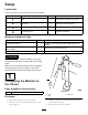


5.Adjustthemachinehitchclevistothesamelevelas
thetractorhitchasfollows:
A.Removetheboltsandlocknutsthatsecurethe
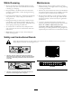
hitchclevis(Figure3)tothemachineframe.
Figure3
1.Clevishitch
B.Raiseorlowerthehitchclevistotheposition
approximatelylevelwiththetractorhitch.
C.Secureitwiththeboltsandlocknutsthatwere
previouslyremoved.
6.Connectthetractorhitchtothemachineclevishitch
withthehitchpinandclevis.
7.Removethejackpin,rotatethejackupwardtothe
storageposition.
2
AdjustingthePTOShaft
Length
Partsneededforthisprocedure:
1
PTOshaft
Procedure
AlongPTOshaftissuppliedwiththemachineto
accommodatelargevariationsinthetractor’sPTO.Formost
tractors,thisshaftistoolongandmustbecuttothecorrect
lengthordamagemayresult.
1.Measurethedistancefromthelockgrooveofthe
tractorPTOshafttothelockgrooveofthemachine
impellerinputshaft.
Note:Recordthisdimension.
2.FullycollapsethePTOshaftandmeasurethedistance
betweenthelockpincollars.
Note:Recordthisdimension.
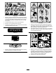
3.Atitsshortestlength,the2halvesofthePTOshaft
musthaveatleast37mm(1-1/2inches)ofadditional
clearancetocollapse(Figure4).
Note:IfthedimensioninStep1isnotatleast37mm
(1-1/2inches)greaterthanthedimensioninStep2,
thePTOshaftistoolong;proceedtostep4.Ifthereis
enoughclearancetoallowthePTOshafttocollapse,
proceedtoStep9.
Figure4
1.PTOshaft
4.Usethefollowingcalculationtoestablishhowmuch
shortertheshaftmustbe,whenconnected,toensurea
clearanceof37(1-1/2inches):
A.SubtractthedimensionrecordedinStep2from
thedimensionrecordedinStep1.
Note:Recordthisdimension.
B.SubtracttheresultinStepAfrom37mm(1-1/2
inches).
Note:ThePTOshaftmustbeshortenedbythis
amount.
5.Usingahacksaw,shortentheguardsandthesteeltubes
bythecalculatedlength.
Note:CutbothhalvesofthePTOshaft.
6.Deburrtheendsofthesteeltubesinternallyand
externally.
7.Removealldebrisfromthetubesections.
8.Greasethesteeltubesliberally.
9.AssemblethePTOshaftandsecureittothemachine
andtractor.
9