
Service Manual


Workman GTX Gasoline Page 6 -- 43 Chassis
Disassembly ( Fig. 41)
1. Park vehicle on a level surface, stop engine, engage
parking brake and remove key from the key switch.
2. Remove seat base assembly with attached seats
from vehicle.
3. If right hand seat base side is to be removed from ve-
hicle (Fig. 42):
A. Remove battery from vehicle (see Battery Ser-
vice in the Service and Repairs section of Chapter 5
-- Electrical System).
B. Support seat base side and remove two (2)
screws that secure seat base side to battery base
and
C. Remove right hand seat base side from vehicle.
4. Remove remaining seat base supports from vehicle
as needed using Figure 41 as a guide.
5. If needed, remove seats from seat base (Fig. 43).
Assembly (Fig. 41)
1. Secure seats to seat base if they were removed (Fig.
43). Torque cap screws from 90 to 110 in--lb (10.2 to
12.4 N--m).
2. Install all removed seat base supports to vehicle us-
ing Figure 41 as a guide. When securing seat base sup-
ports to vehicle, use torque values identified in Figures
41 and 42.
3. If battery was removed from vehicle, install battery
(see Battery Service in the Service and Repairs section
of Chapter 5 -- Electrical System).
4. Install seat base assembly with attached seats to v e-
hicle.
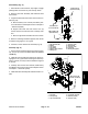
1. RH seat base side
2. Battery
3. Cap screw
4. Flat washer
5. Battery clamp channel
6. Battery tray
7. Screw (4 used)
8. Battery base
9. Screw (2 used)
10. Flange nut
11. Battery clamp plate
Figure 42
2
3
6
8
9
10
11
1
5
7
4
7
40 to 45 in--lb
(4.6 to 5.0 N--m)
18 to 22 in--lb
(2.1 to 2.4 N--m)
200 to 230 in--lb
(23to25N--m)
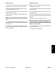
1. Seat base
2. Seat (2 used)
3. Cap screw (8 used)
4. Flat washer (8 used)
5. Retainer (2 used)
6. Screw (4 used)
Figure 43
2
3
6
1
5
4
90 to 110 in--lb
(10.2 to 12.4 N--m)
Chassis