
Operator's Manual

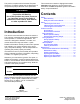


AdjustingtheOperating
Height
Theoperatingheightissetatthefactoryfor13-mm
(1/2inch)highgrass.Youcanadjustitfrom13to76
mm(1/2to3inches)byrepositioningthecastor-wheel
spacersandrelocatingthecapscrewsthatsecurethe
castorbeamstotheheight-adjustmentplates.
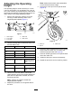
1.Removethecapscrews,washers,andnuts
securingacastor-assemblybeamtothe
height-adjustmentplates(Figure7).
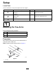
g263711
Figure7
1.Grassheight
4.Rearslots
2.Frontcastor5.Rearcastor
3.Frontslots
2.Usethefollowingtabletodeterminewhichfront
andrearslotstouse.
FrontCastorHeightofcutBackCastor
Setthedeckatthetopfrontslotandthetoprearslot.
2spacers(1/2
inch)
13mm(1/2inch)1spacer(1/2inch)
1spacer(1/2inch)25mm(1inch)3spacers(1/2inch)
1spacer(1/4inch)38mm(1-1/2inch)5spacers(1/2inch)
Setthedeckatthetopfrontslotandthemiddlerearslot.
1spacer(1/8inch)51mm(2inch)4spacers(1/2inch)
and1spacer(1/4
inch)
Setthedeckatthetopfrontslotandthebottomrearslot.
Nospacers
64mm(2-1/2inch)4spacers(1/2inch)
Nospacers
76mm(3inch)5spacers(1/2inch)
and1spacer(1/4
inch)
3.Usethefrontandrearslotstosecurethe
castor-assemblybeamtotheheight-adjustment
platewiththecapscrews,washers,andnuts
previouslyremoved.
Note:Positionthewashersoutsidethe
height-adjustmentplates.
4.Repeattheprocedurefortheoppositesideof
thedeck.
Note:Makesurethatbothcastorassemblies
aremountedatthesameheight.
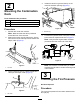
5.Removetheclevispinfromthespindleshaft
(Figure8).
g011297
Figure8
1.Clevispin3.Castorarm
2.Spacer
6.RemoveoraddC-shapedspacerstothespindle
shaft,belowthecastorarm,toachievethe
desiredheight(seetableandFigure8).
7.Placeallremainingspacersonthespindleshaft
abovethecastorarm.
8.Installtheclevispintosecuretheassembly.
9.Repeattheprocedureontheremainingcastors.
7