
Operator's Manual

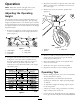


Figure13
1.Tensionerguide
3.Capscrew(backofframe)
2.Capscrew&nut
4.Tensioner
3.Removecapscrewandnutsecuringtensionerguide
todrivemount(Figure13).Belttensionwillbe
releasedwhencapscrewisremoved.
4.Positionalargewrenchontensioner.Rotate
tensionerclockwiseuntildecalarrowisalignedwith
15degreesontensionertube.
5.Insertcapscrewintoalignedguideholesandsecure
withnut.Ifholesarenotexactlyaligned,rotateguide
tothenexthigherholeuntilaligned.
6.Tightencapscrew,onbacksideofframetolock
tensioner.
7.Installthemotorshieldwiththefastenerspreviously
removed.
ReplacingtheFingerBelts
1.Loosennutsandwasherssecuringngerpinchers
torotor(Figure14).
2.Removeoldbeltngers.
3.Installnewbeltngers.Beltngerstoextendfrom
ngerpinchersapproximately4inches.
4.Tightennutssecuringassembly.
Figure14
1.Fingerpincher
3.Beltnger
2.Rotor
Figure15
1.3.63inches
3.Keyedshaft
2.Flatsidetobelt4.Brushrotation
ReplacingtheFlailKnives
Whenailknifeedgesbecomecurvedfromwear,they
shouldbereversedorreplaced.
1.Removerollpinsecuringmountingpintoailrotor
(Figure16).
2.Slidemountingpinfromrotorallowingremovalof
ailknivesandspacers(Figure16).
3.Inspectspacersandmountingpinsforwearand
replaceasnecessary.
4.Assembletheailknives(Figure16)asfollows:
•Startingatendofrotor,assembleaspacer
andaailknifewithhanger,thenthreemore
spacers.Continuepatternuntilpinisfull.Secure
mountingpintorotorwithrollpin.
Note:Counttherotorangeasaspacer.
12