
Installation Instructions

1
All Rights Reserved
Printed in the USA
W 2005 by The Toro Company
8111 Lyndale Avenue South
Bloomington, MN 55420-1196
Windrow Kit
Pro Sweep 5200
Model No. 07087
Form No. 3352–713
Installation Instructions
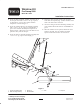
1. Secure the blade mounting assembly to the left end of
the sweeper frame with a 7/16 x 3–14” lg. capscrew,
(3) flatwashers, a spacer and a locknut. Position
components as shown in figure 1.
2. Secure the windrow blade to the mounting assembly
with a 7/16 x 3–14” lg. capscrew, (2) flatwashers, a
spacer and a locknut. Assembly the components as
shown in figure 1. The longer end of the blade is to be
positioned away from the sweeper.
3. Secure the chain to the blade mounting assembly with
a 3/8 x 1–1/4” lg. capscrew and nut (Fig. 1).
4. Secure the other end of the chain to the slot in the
frame with the snap link (Fig. 1).There should be some
slack in the chain when connected.
5. Grease the fitting on the blade mounting assembly and
on the windrow blade hub with No. 2 Lithium Based
grease.
6. When the windrow is not required, unhook the chain
from the snap link, pivot the windrow assembly
upward and hook the chain at the raised level.
1
2
3
5
6
3
4
Figure 1
1. Left end of sweeper frame
2. Blade mounting assembly
3. Spacer (2)
4. Windrow blade
5. Chain 6. Snap link