
Installation Instructions

1
All Rights Reserved
Printed in the USA
W 2005 by The Toro Company
8111 Lyndale Avenue South
Bloomington, MN 55420-1196
Actuator Kit
Pro Sweep 5200
Model No. 07088
Form No. 3352–717
Installation Instructions
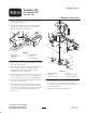
1. Remove the hitch pin securing the actuator arm to the
front actuator tab (Fig. 1).
2. Remove the capscrew, (2) flat washers and locknut
securing the actuator arm to the rear actuator tab
(Fig. 1). Remove the actuator arm.
1
4
2
5
3
Figure 1
1. Actuator arm
2. Welded tab end of
actuator arm
3. Front actuator tab
4. Hitch pin
5. Rear actuator tab
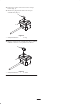
3. Insert a spacer tube into the mounting hole in the body
end of the actuator (Fig. 2).
4. Insert the body end of the actuator and the spacer into
the rear actuator tab (Fig. 2). Align the actuator
mounting hole and the spacer with the smaller
mounting holes in the actuator tab.
5. Loosely mount the actuator and the tube spacer to the
actuator tab with a 3/8–16 x 2–1/2” lg. capscrew, (2)
.406 x .063 flat washers and a 3/8–16 locknut (Fig. 2).
6. Insert a spacer tube into the mounting hole in the rod
end of the actuator (Fig. 2).
7. Insert the rod end of the actuator, the tube spacer and
(2) spacers into the front actuator tab (Fig. 2). Align
the actuator rod mounting hole, the tube spacer and the
(2) spacers with the smaller mounting holes in the
actuator tab.
1
2
4
3
2
4
5
6
Figure 2
1. Actuator (body end)
2. Spacer tube
3. Actuator (rod end)
4. Spacer
5. Actuator wire harness
6. Sweeper wire harness
8. Loosely mount the actuator rod, the tube spacer and
the (2) spacers to the actuator tab with a 3/8–16 x
2–1/2” lg. capscrew, (2) .406 x .063 flat washers and a
3/8–16 locknut (Fig. 2).
9. Tighten the actuator mounting fasteners.