Form No. 3407-497 Rev D Workman® GTX Utility Vehicle Model No. 07130—Serial No. 316000001 and Up Model No. 07130TC—Serial No. 316000001 and Up Register at www.Toro.com.
on the product. Write the numbers in the space provided. This product complies with all relevant European directives; for details, please see the separate product specific Declaration of Conformity (DOC) sheet.
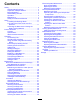
Contents Electrical System Maintenance ........................... 40 Servicing the Battery......................................... 40 Replacing the Fuses ......................................... 43 Maintaining the Headlights ............................... 43 Drive System Maintenance .................................. 45 Maintaining the Tires ........................................ 45 Inspecting the Steering and Suspension Components .................................................
Before Operating Safety • Become familiar with the controls and know how to shut off the engine quickly. Improper use or maintenance by the operator or owner can result in injury. To reduce the potential for injury, comply with these safety instructions and always pay attention to the safety-alert symbol, which means Caution, Warning, or Danger—personal safety instruction. Failure to comply with the instruction may result in personal injury or death.
• Never store the machine or fuel container where • • • there is an open flame, spark, or pilot light, such as on a water heater or on other appliances. Remove equipment from the truck or trailer and refuel it on the ground. If this is not possible, then refuel such equipment with a portable container rather than from a fuel-dispenser nozzle. If fuel is spilled on clothing, change clothing immediately. Never overfill the fuel tank. Replace the fuel cap and tighten it securely.
Operating on Hills • Passengers should sit in the designated seating positions only. Do not allow passengers to sit in the cargo box. WARNING • The operator and passengers should remain Operating the machine on a hill may cause tipping or rolling of the machine, or the engine may stall and you could lose headway on the hill. This could result in personal injury. • Do not operate the machine on excessively steep slopes.
Maintenance terrain, uneven ground, and near curbs, holes, and other sudden changes in terrain. Loads may shift, causing the machine to become unstable. • Before servicing or making adjustments to the machine, shut off the engine, engage the parking brake, and remove the key from the key switch to prevent accidental starting of the engine. WARNING Sudden changes in terrain may cause abrupt steering wheel movement, possibly resulting in hand and arm injuries.
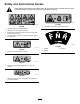
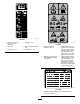
Safety and Instructional Decals Safety decals and instructions are easily visible to the operator and are located near any area of potential danger. Replace any decal that is damaged or missing. decal131-8410 131-8410 decal99-7345 99-7345 1. Fire hazard—shut off the engine before fueling. 1. Warning—read the Operator's Manual. 2. Warning—do not touch the hot surface. 3. Entanglement hazard, belt—stay away from moving parts; keep all guards in place. 4.
decal131-8552 131-8552 1. Read the Operator's Manual for fuse information. 2. Horn; 30 A 3. Main power; 15 A 4. Headlights; 10 A decal131-8414 131-8414 5. USB power point/options; 10 A 6. Optional lift kit; 15 A 1. Warning—read the Operator's Manual. 3. Tipping hazard—drive slowly across or up slopes; take turns slowly; do not exceed speeds of 25 kph (16 mph); drive slowly when hauling cargo; drive slowly on uneven terrain. 2. Warning—receive proper training before operating the machine. 4.
decal131-8598 131-8598 1. Maximum bed weight 91 kg (200 lb) 2. Maximum trailer weight 454 kg (1,000 lb) decal131-8413 131-8413 1. Horn 4. Engine—start 2. Off 5. To start the engine: 1) Sit in the operator's position; 2) Disengage the parking brake; 3) Turn the key to the engine START position; 4) Engage the choke; 5) Press down on the pedal. 3. On 6. To shut off the engine: 1) Release the pedal; 2) Engage the parking brake; 3) Turn the key to the OFF position; 4) Remove the key from the key switch.
Setup Loose Parts Use the chart below to verify that all parts have been shipped. Procedure Description Use Qty. 1 Steering wheel Cover Washer (1/2 inch) 1 1 1 Install the steering wheel (TC Models only). 2 No parts required – Check the fluid levels and tire pressure.
• Complete the Predelivery Inspection Form. 2 • Review the Certificate of Quality. Checking the Fluid Levels and Tire Pressure No Parts Required Procedure 1. Check the engine-oil level before and after the engine is first operated; refer to Checking the Engine-Oil Level (page 36). 2. Check the brake fluid level before the engine is first operated; refer to Checking the Brake-Fluid Level (page 50). 3.
Product Overview g033925 Figure 4 1. Hood latch 3. Steering wheel 5. Towing tongue 2. Shift lever 4. Cargo box 6. Fuel cap 7. Cargo-box lever g034517 Figure 5 1. Passenger handhold 3. Rear cargo-box-accessory mount 2. Parking-brake lever 4.
Controls g033921 Figure 6 1. Steering wheel 6. USB power point 2. Gear-shift indicator 7. Parking-brake lever 3. Gear-shift lever 4. Horn button (TC models only) 8. Choke control 9. Brake pedal 5. Key switch 10. Accelerator pedal CAUTION Accelerator Pedal Operating a machine with worn or incorrectly adjusted brakes can may result in personal injury. Use the accelerator pedal (Figure 6) to vary ground speed of the machine. Pressing down the accelerator pedal starts the engine.
Key Switch parking-brake lever toward you to release pressure, and then push the parking-brake lever forward (Figure 8). The key switch is located to the left of the parking-brake lever on the control panel (Figure 6). The key switch has 3 positions: OFF, ON, and START . There are 2 modes of starting the machine: • Pedal Start—turn the key switch to the ON position, press down the accelerator pedal, then release your foot from the accelerator pedal.
Choke Control Light Switch The choke control is located on the control panel. Use the choke to help start a cold engine by pulling the choke control outward (Figure 6). After the engine starts, adjust the choke to keep the engine running smoothly. As the engine warms up, push in the choke control to the OFF position. The light switch is located to the left of the steering column (Figure 10). Use the light switch to illuminate the headlights.
Fuel Gauge The fuel gauge (Figure 11) is located on the fuel tank next to the filler cap, at the left side of the machine. The gauge displays the amount of fuel in the tank. g033956 Figure 11 1. Empty 4. Full 2. Half full 5. Fuel-tank cap 3. Needle 6. Fuel gauge Passenger Handholds The passenger handholds are located on the outside of each seat (Figure 12). g033955 Figure 12 Passenger Side Shown 1.
Specifications Note: Specifications and design are subject to change without notice. Base weight 397 kg (875 lb) Rated capacity (on level ground) 544 kg (1,200 lb) total, including 90.
Operation CAUTION machine from the normal operating position. If a load is concentrated near the back of the cargo box when you release the latches, the box may unexpectedly tip open, injuring you or bystanders. Think Safety First • Center loads in the cargo box, if possible. Carefully read all safety instructions and symbols in the safety section. Knowing this information could help you or bystanders avoid injury.
Opening the Tailgate Raising the Cargo Box to the Service Position 1. Ensure that the cargo box is down and latched. 1. Pull the lever on left, inside of the cargo box toward you and lift the cargo box up (Figure 13). 2. Using both hands, raise the tailgate using the ridge near the top of the tailgate (Figure 15). 2. Pull prop rod into the service position detent slot, securing the box for maintenance (Figure 14). 3.
Using the Rear Cargo-Box-Accessory Mount Closing the Tailgate If you unloaded loose material such as sand, landscaping rock, or wood chips from the cargo box of the machine, some of the material that you unloaded may have lodged in the hinge area of the tailgate. Perform the following steps before closing the tailgate. 1. 2. Use the rear cargo-box-accessory mount to attach accessories to the rear of the machine. Use your hands to remove as much of the material from the hinge area as possible.
Performing Pre-Starting Checks Checking the Tire Pressure Service Interval: Before each use or daily Service Interval: Before each use or daily Check the following items each time you begin using the machine for the day: Tire Air Pressure Range: 165 to 207 kPa (24 to 30 psi) • Check brake fluid levels, and add the specified pressure indicated on the sidewall of the tire. Important: Do not exceed the maximum air brake fluids as needed; refer to Checking the Brake-Fluid Level (page 50).
Filling the Fuel Tank DANGER In certain conditions, fuel is extremely flammable and highly explosive. A fire or explosion from fuel can burn you and others and can damage property. • Fill the fuel tank outdoors, in an open area, when the engine is cold. Wipe up any fuel that spills. • Never fill the fuel tank inside an enclosed trailer. • Do not fill the fuel tank completely full. Add fuel to the fuel tank until the level is 1 inch (25 mm) below the bottom of the filler neck.
Starting the Engine 1. Note: The stopping distance may vary depending on the machine load and speed. Sit in the operator seat, insert the key into the key switch, and rotate the key clockwise to the ON or START position. Parking the Machine There are 2 modes of starting the machine: 1. Stop the machine using the service brakes by pressing and holding the brake pedal. 2. Engage the parking brake by pulling the parking-brake lever toward you. 3.
Loading the Cargo Box Material Density Maximum Cargo Box Capacity (on level ground) Gravel, dry 1522 kg/m3 (95 lb/ft3) Full limit the weight of the load that you carry in the cargo box as described in Specifications (page 18) and on the gross vehicle weight (GVW) tag of the machine.
Transporting the Machine Towing the Machine Use a trailer with full-width ramps to move the machine a long distance. Make sure that the machine is securely bound to the trailer. Refer to Figure 20 and Figure 21 for the location of the tie-down points on the machine. In case of an emergency, the machine can be towed for a short distance. However, we do not recommend this as a standard operating procedure.
Maintenance Note: Download a copy of the electrical schematic by visiting www.Toro.com and searching for your machine from the Manuals link. Note: Determine the left and right sides of the machine from the normal operating position. Important: Refer to your engine owner's manual for additional maintenance procedures. Recommended Maintenance Schedule(s) Maintenance Service Interval Maintenance Procedure After the first 5 hours • Change the engine oil.
Daily Maintenance Checklist Duplicate this page for routine use. Maintenance Check Item For the week of: Monday Tuesday Wednesday Thursday Friday Saturday Sunday Check brake and parking brake operation. Check gear shift/neutral operation. Check fuel level. Check engine-oil level. Check transaxle-fluid level. Inspect air filter. Inspect engine-cooling fins. Check unusual engine noises. Check unusual operating noises. Check tire pressure. Check fluid leaks. Check instrument operation.
Pre-Maintenance Procedures Important: Whenever the engine is run for routine maintenance and/or engine diagnostics, the rear wheels of the machine should be 25 mm (1 inch) off the ground, with the rear axle supported on jack stands. Maintaining the Machine under Special Operating Conditions • The lifting point at the front of the machine is at the front of the frame behind the towing tongue (Figure 22).
Accessing the Hood Removing the Seat Assembly Raising the hood 1. Push the seat assembly forward and lift the assembly upward until the retainer brackets clear the seat-base panel (Figure 25). Lift up the handle of the rubber latches at each side of the hood (Figure 24). g034117 Figure 25 1. Seat-base panel 3. Retainer brackets 2. Seat assembly Installing the Seat Assembly g034045 Figure 24 2.
Lubrication Greasing the Front Wheel Bearings Greasing the Machine Service Interval: Every 300 hours Service Interval: Every 100 hours/Yearly (whichever comes first)—Grease the bearings and bushings. Grease the machine more frequently when using it for heavy-duty operations. Grease specification: Mobilgrease XHP™-222 Removing the Hub and Rotor 1. Lift the front of the machine and support it with jack stands. 2. Remove the 4 lug nuts that secure the wheel to the hub (Figure 29). Grease Type: No.
g192347 Figure 32 1. Spindle 2. Hub and rotor assembly g033047 Figure 30 1. Flange-head bolts (3/8 x 3/4 inch) 3. Caliper bracket (brake assembly) 2. Spindle 4. Remove the dust cap from the hub (Figure 31). g192346 Figure 31 1. Cotter pin 4. Spindle nut 2. Spindle 5. Nut retainer 3. Tab washer 6. Dust cap 5. Remove the cotter pin and nut retainer from the spindle and spindle nut (Figure 31). 6.
Installing the Hub and Rotor Greasing the Wheel Bearings 1. 1. Remove the outboard bearing and bearing race from the hub (Figure 33). Apply a light coat of the specified grease to the spindle (Figure 34). g192344 Figure 34 g033050 Figure 33 1. Seal 4. Bearing cavity (hub) 2. Inboard bearing 5. Outboard-bearing race 3. Inboard-bearing race 6. Outboard bearing 2. Remove the seal, inboard bearing from the hub (Figure 33). 3. Wipe clean the seal and check for wear and damage. 1.
g192345 Figure 35 1. Cotter pin 3. Dust cap 2. Nut retainer 9. Install the cotter pin and bend each legs around the retainer (Figure 35). 10. Install the dust cap onto the hub (Figure 35). 11. Repeat steps 1 through 10 for the hub and rotor at the other side of the machine. Installing the Brakes and Wheels 1. Clean the 2 flange-head bolts (3/8 x 3/4 inch) and apply a coat of medium-strength thread-locking compound to the threads of the bolts. 2.
Engine Maintenance Servicing the Air Cleaner Service Interval: Every 100 hours Replace the air-filter element sooner if dirty or damaged. Note: Service the air cleaner more frequently (every few hours) if operating conditions are extremely dusty or sandy. Servicing the Air-Cleaner Cover Service Interval: Every 50 hours—Remove the air-cleaner cover and clean out the debris. Do not remove the filter. Check the air-cleaner body for damage which could cause an air leak. Replace a damaged air-cleaner body.
Servicing the Air-Cleaner Filters Important: Do not press on the soft inside area of the filter. Service Interval: Every 100 hours More frequently in extreme dusty or dirty conditions. 1. 6. Gently slide the primary filter out of the air-cleaner body (Figure 37). Note: Avoid knocking the filter into the side of Install the air-cleaner cover with the side indicated as “UP” facing upward and secure the latches (Figure 37). the body.
Changing the Engine Oil 1. Start the machine and let the engine run for a few minutes. 2. Park the machine on a level surface, engage the parking brake, rotate the key switch to the OFF position, and remove the key. 3. Raise the cargo box and secure it with the prop rod; refer to Raising the Cargo Box to the Service Position (page 20). 4. Change the engine oil as shown in Figure 40.
Servicing the Spark Plug Checking and Replacing the Spark Plug Service Interval: Every 100 hours/Yearly (whichever comes first) Replace the spark plug if necessary. Type: Champion RC12LC4 Air Gap: 0.76 mm (0.03 inch) Important: A cracked, fouled, dirty, or malfunctioning spark plug must be replaced. Do not sand-blast, scrape, or clean electrodes by using a wire brush because grit may eventually release from the plug and fall into the cylinder. The result is usually a damaged engine.
Fuel System Maintenance Inspecting Fuel Lines and Connections Service Interval: Every 400 hours/Yearly (whichever comes first) Inspect the fuel lines, fittings, and clamps for signs of leaking, deterioration, damage, or loose connections. Note: Repair any damaged or leaking fuel system component before using the machine. Replacing the Fuel Filter Service Interval: Every 400 hours/Yearly (whichever comes first) 1. Shut the engine off and remove the key from the key switch. 2.
Servicing the Carbon Canister Electrical System Maintenance Checking the Air Filter for the Carbon Canister Servicing the Battery Battery voltage: 12 V with 300 cold-cranking amps at -18°C (0°F). Service Interval: After the first 50 hours Every 200 hours WARNING Check the opening at the bottom of the air filter for the carbon canister to ensure that it is clean and free of debris and obstructions (Figure 43).
Disconnecting the Battery Removing the Battery WARNING Incorrect battery cable routing could damage the machine and cables, causing sparks. Sparks can cause the battery gasses to explode, resulting in personal injury. 1. Disconnect the battery cables; refer to Disconnecting the Battery (page 41). 2. Remove the battery as shown in Figure 45. • Always disconnect the negative (black) battery cable before disconnecting the positive (red) cable.
Installing the Battery 1. Connecting the Battery Install the battery as shown in Figure 46. Connect the battery as shown in Figure 47. g034315 Figure 47 Charging the Battery WARNING Charging the battery produces gasses that can explode. Never smoke near the battery and keep sparks and flames away from battery. Important: Always keep the battery fully charged (1.260 specific gravity). This is especially important to prevent battery damage when the temperature is below 0°C (32°F). 1.
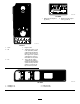
Replacing the Fuses Maintaining the Headlights There are 4 fuses in the electrical system. They are located beneath the seat assembly (Figure 48). Replacing the Bulbs Note: If you install the optional lift kit, you will receive another fuse block to install next to the fuse block installed currently.
Replacing the Headlight with the slots in the headlight housing (Figure 49). 6. Secure lamp assembly by turning it 1/4 turn clockwise (Figure 49). 7. Connect the electrical connector for the harness to the connector of the new lamp assembly (Figure 49). 8. 1. Disconnect the battery; refer to Disconnecting the Battery (page 41). 2. Open the hood; refer to Accessing the Hood (page 30). 3. Disconnect the electrical connector for the harness from the connector of the lamp assembly (Figure 50).
Adjusting the Headlights Drive System Maintenance Use the following procedure to adjust the headlight beam position whenever a headlight assembly is replaced or removed. 1. Turn the key switch to the ON position, and turn on the headlights. 2. At the back of the headlight assembly, rotate adjustment screws (Figure 50) to pivot the headlight assembly and align the position of the cast beam. 3. Maintaining the Tires Service Interval: Every 100 hours—Check the condition of the tires and rims.
Inspecting the Steering and Adjusting the Front Wheel Toe-in Suspension Components Service Interval: Every 100 hours—Inspect the steering and suspension for loose or damaged components. Service Interval: Every 100 hours/Yearly (whichever comes first)—Check the front wheel toe-in. With the steering wheel at the centered position (Figure 51), turn the steering wheel to the left or right.
g009235 Figure 54 1. Tire center line—back 2. Tire center line—front 4. 3. Axle center line g035761 Figure 56 1. Fill plug If the measurement does not fall within 0 +/– 3 mm (0 +/– 1/8 inch), loosen the jam nuts at the outer end of the tie rods (Figure 55). 2. Drain plug 3. If the fluid level is low, remove the fill plug and add the specified fluid until it runs out of the hole (Figure 56). 4. Replace the fill plug and torque it to 20 to 27 N∙m (15 to 20 ft-lb).
Adjusting the Neutral Gear-Shift Position Checking the Neutral Gear-Shift Position 1. Service Interval: Every 100 hours When performing routine maintenance and/or engine diagnostics, the transaxle must be shifted into NEUTRAL. The machine has a NEUTRAL position on the gear-shift selector, which controls the neutral in the transaxle. The following steps should be taken to make sure that the neutral shift lever operates the transaxle neutral correctly: 1.
Maintaining the Primary-Drive Clutch Cooling System Maintenance Service Interval: Every 400 hours/Yearly (whichever comes first) Cleaning the Engine-Cooling Areas CAUTION The dust in the clutch becomes airborne and could damage your eyes, or you could inhale it, causing breathing difficulties. Service Interval: Every 100 hours Clean the cooling system twice as often during special operating conditions; refer to Maintaining the Machine under Special Operating Conditions.
Brake Maintenance Note: If you cannot adjust the parking brake to the required tension, the brake pads may be worn and need to be replace. Contact your Authorized Toro Service Dealer for assistance. Checking the Parking Brake 1. 2. Engage the parking brake by pulling the parking-brake lever toward you, until you feel tension. Checking the Brake-Fluid Level If you do not feel tension when pulling the parking-brake toward you within 11.4 to 16.
Belt Maintenance Servicing the Drive Belt Checking the Drive Belt Service Interval: After the first 8 hours Every 200 hours g002136 Figure 61 1. Brake-fluid reservoir 4. 1. Park the machine on a level surface, engage the parking brake, rotate the key switch to the OFF position, and remove the key. 2. Raise the cargo box and secure it with the prop rod; refer to Raising the Cargo Box to the Service Position (page 20). 3. Shift the transmission into NEUTRAL. 4.
Replacing the Drive Belt 1. Raise the cargo box; refer to Raising the Cargo Box to the Service Position (page 20). 2. Shift the transmission into Neutral, engage the parking brake, rotate the key switch to the OFF position, and remove the key. 3. Rotate and route the belt over the secondary clutch (Figure 62). 4. Remove the belt from the primary clutch (Figure 62).
Cleaning Washing the Machine Wash the machine as needed. Use water alone or with a mild detergent. You may use a rag when washing the machine; however, the hood loses some of its luster. Important: Do not use power-washing equipment to wash the machine. Power-washing equipment may damage the electrical system, loosen important decals, or wash away necessary grease at friction points. Avoid excessive use of water near the control panel, engine, and battery.
Storage 1. 2. E. Choke the engine. F. Start and run the engine until it does not start again. Position the machine on a level surface, engage the parking brake, rotate the key switch to the OFF position, and remove the key. 9. Clean the dirt and grime from the entire machine, including the outside of the cylinder-head fins of the engine and blower housing. 10. With the spark plugs removed from the engine, pour 2 tablespoons of engine oil into the spark plug hole. 11.
European Privacy Notice The Information Toro Collects Toro Warranty Company (Toro) respects your privacy. In order to process your warranty claim and contact you in the event of a product recall, we ask you to share certain personal information with us, either directly or through your local Toro company or dealer. The Toro warranty system is hosted on servers located within the United States where privacy law may not provide the same protection as applies in your country.
The Toro Warranty A Two-Year Limited Warranty Conditions and Products Covered The Toro Company and its affiliate, Toro Warranty Company, pursuant to an agreement between them, jointly warrant your Toro Commercial product (“Product”) to be free from defects in materials or workmanship for two years or 1500 operational hours*, whichever occurs first. This warranty is applicable to all products with the exception of Aerators (refer to separate warranty statements for these products).