Form No. 3421-904 Rev C Workman® GTX Electric Utility Vehicle Model No. 07043—Serial No. 401400001 and Up Model No. 07131TC—Serial No. 400000000 and Up Register at www.Toro.com.
This product complies with all relevant European directives; for details, please see the separate product specific Declaration of Conformity (DOC) sheet. WARNING CALIFORNIA Proposition 65 Warning The power cord on this product contains lead, a chemical known to the State of California to cause birth defects or other reproductive harm. Wash hands after handling.
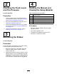
Contents Maintaining the Headlights ............................... 38 Drive System Maintenance .................................. 40 Maintaining the Tires ........................................ 40 Inspecting the Steering and Suspension Components ................................................. 40 Adjusting the Front Wheel Alignment ................ 41 Checking the Transaxle-Fluid Level .................. 42 Changing the Transaxle Fluid ........................... 42 Brake Maintenance .................
Safety This machine meets the requirements of SAE J2258. General Safety This product is capable of causing personal injury. Always follow all safety instructions to avoid serious personal injury. Using this product for purposes other than its intended use could prove dangerous to you and bystanders. • Read and understand the contents of this Operator’s Manual before you start the motor. Ensure that everyone using this product knows how to use it and understands the warnings.
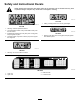
Safety and Instructional Decals Safety decals and instructions are easily visible to the operator and are located near any area of potential danger. Replace any decal that is damaged or missing. decal115-7739 115-7739 1. Falling, crushing hazard—do not carry passengers. decal99-7345 99-7345 1. Warning—read the Operator's Manual. 2. Hot surface/burn hazard—stay a safe distance away from the hot surface. 3. Entanglement hazard, belt—stay away from moving parts; keep all guards in place.
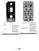
decal131-8414 131-8414 decal131-8412 131-8412 1. Horn 2. Forward 3. Neutral 4. Reverse 5. Off 6. On 7. Turning on—1) Sit in the driver's seat; 2) Disengage the parking brake; 3) Turn the key switch to the start position; 4) Push down on the pedal. 8. Turning off—1) Release the pedal; 2) Engage the parking brake; 3) Turn the key switch to the stop position; 4) Remove the key from the key switch. 6 1. Warning—read the Operator's Manual. 3.
decal131-8527 131-8527 2. Eco mode 1. Performance mode decal131-8495 131-8495 1. The battery is empty. 3. The battery is charged. 2. The battery is almost charged. 4. Charger fault; refer to the charger manual for the fault codes. decal131-8551 131-8551 3. Optional lift kit (15 A) 1. Read the Operator’s Manual for fuse information. 2. Horn (30 A) 4. Main power (10 A) decal131-8506 131-8506 1. Solid light—unit is prepared for operation. decal131-8598 2.
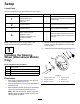
Setup Loose Parts Use the chart below to verify that all parts have been shipped. Procedure 1 2 3 4 Description Qty. Use Steering wheel Steering wheel cover Washer (1/2 inch) Dust cover 1 1 1 1 Install the steering wheel (International models only). No parts required – Check the fluid levels and tire pressure. No parts required – Burnish (break-in) the brakes.
2 4 Checking the Fluid Levels and Tire Pressure Reading the Manual and Viewing the Setup Material No Parts Required Parts needed for this procedure: Procedure 1. Check the water level in the batteries before you operate the machine; refer to Checking the Water Level of the Batteries (page 36). 2. Ensure that the batteries are charged; refer to Charging the Batteries (page 34). 3. Check the brake-fluid level before you operate the machine; refer to Checking the Brake-Fluid Level (page 43). 4.
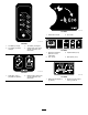
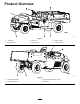
Product Overview g034154 Figure 4 1. Hood latch 3. Cargo bed 5. Battery charger 2. Steering wheel 4. Towing tongue 6. Cargo-bed lever g034544 Figure 5 1. Passenger handhold 3. Rear cargo-bed-accessory mount 2. Parking-brake lever 4.
Controls Control Panel g034161 Figure 6 1. Light switch 7. Parking-brake lever 2. Hour meter 8. Brake pedal 3. Battery-discharge indicator 9. Accelerator pedal 4. Horn button (International models only) 10. USB power point 5. Gear-shift selector 11. Status-indicator light 6. Key switch Accelerator Pedal Brake Pedal Use the accelerator pedal (Figure 6) to vary ground speed of the machine. Pressing down the accelerator pedal starts the machine. Pressing the pedal farther increases ground speed.
Parking-Brake Lever Direction Selector The parking-brake lever is located on the control panel (Figure 7). The direction selector is located to the left of the parking-brake lever. The direction selector has 3 positions: FORWARD , REVERSE, and NEUTRAL (Figure 6). Whenever you shut off the engine, engage the parking brake to prevent the machine from accidentally moving. If the machine is parked on a steep grade, ensure that you engage the parking brake.
Key Switch Status-Indicator Light Use the key switch (Figure 6), to run and shut off the machine. The status-indicator light is located to the right of the parking-brake lever on the control panel (Figure 6). The key switch has 2 positions: ON and OFF. Rotate the key clockwise to the ON position to operate the machine. When you stop the machine, rotate the key counterclockwise to the OFF position to shut off the machine. Remove the key whenever you leave the machine.
Specifications Note: Specifications and design are subject to change without notice.
Operation Before Operation Before Operation Safety General Safety • Never allow children or untrained people to g001055 operate or service the machine. Local regulations may restrict the age of the operator. The owner is responsible for training all operators and mechanics. Figure 11 • Become familiar with the safe operation of the Understanding and Using the Battery System equipment, operator controls, and safety signs. • Know how to stop the machine and shut off the motor quickly.
Using the Battery System When your batteries are fully charged, the tenth bar (far right) illuminates on the battery-discharge indicator (Figure 13). g004049 Figure 12 Battery-Lifetime Table 1. Battery capacity 4. Prime battery life 2. Discharge/charge cycles 5. End of the battery life 3. Break-in period (100 to 150 cycles) After the break-in period, the battery maintains a high capacity for many cycles.
If you continue to use the machine with only 2 bars remaining, bars 1 and 2 alternately flash. During Operation Important: When only the second bar from the During Operation Safety left remains on the battery-discharge indicator, the machine may enter a reduced-speed mode; this mode aids in protecting the batteries, but prolonged operation in this mode can damage the batteries and/or the machine. Avoid draining your batteries down to the second bar from the left to prevent this issue.
• • • • • • • • • • • • Passengers should sit in the designated seating roll over if a wheel goes over the edge or if the edge gives way. When using the machine on public roads, follow all traffic regulations and use any additional accessories that may be required by law, such as lights, turn signals, slow-moving vehicle (SMV) signs, and others as required.
Loading and Dumping Safety 1. • Do not exceed the gross vehicle weight (GVW) • • • Pull the lever on left, inside of the cargo bed toward you and lift the cargo bed up (Figure 15). of the machine when operating it with a load in the cargo bed and/or towing a trailer; refer to Specifications (page 14). Distribute the load in the cargo bed evenly to improve the stability and control of the machine. Before dumping, ensure that there is no one behind the machine.
Opening the Tailgate Raising the Cargo Bed to the Service Position 1. Ensure that the cargo bed is down and latched. 1. Pull the lever on left, inside of the cargo bed toward you and lift the cargo bed up (Figure 15). 2. Using both hands, raise the tailgate using the ridge near the top of the tailgate (Figure 17). 2. Pull prop rod into the service position detent slot to secure the bed for maintenance (Figure 16). 3.
Closing the Tailgate If you unloaded loose material such as sand, landscaping rock, or wood chips from the cargo bed of the machine, some of the material that you unloaded may have lodged in the hinge area of the tailgate. Perform the following steps before closing the tailgate. 1. Use your hands to remove as much of the material from the hinge area as possible. 2. Rotate the tailgate to approximately the 45° position (Figure 18). g034545 Figure 19 1. Receiver 2. “T” handle 2.
Loading the Cargo Bed Refer to the following table for load volume limits with various materials: Use the following guidelines when loading the cargo bed and operating the machine: Material Density Maximum Cargo Bed Capacity (on level ground) • Observe the weight capacity of the machine and limit the weight of the load that you carry in the cargo bed as described in Specifications (page 14) and on the gross vehicle weight tag of the machine.
Towing the Machine CAUTION Loose seats may fall off the machine and trailer when transporting the machine, and the seats may land on another machine or obstruct the roadway. In case of an emergency, you can tow the machine for a short distance; however, this should not be a standard operating procedure. WARNING Remove the seats or make sure that the seats are securely fastened to the coupling in the seat shroud.
Maintenance Note: Determine the left and right sides of the machine from the normal operating position. Note: Download a copy of the electrical schematic by visiting www.Toro.com and searching for your machine from the Manuals link. Important: Refer to your engine owner’s manual for additional maintenance procedures. WARNING Failure to properly maintain the machine could result in premature failure of machine systems, causing possible harm to you or bystanders.
Daily Maintenance Checklist Duplicate this page for routine use. Maintenance Check Item For the week of: Monday Tuesday Wednesday Thursday Friday Saturday Sunday Check brake and parking brake operation. Check gear shift/neutral operation. Check the water level of the batteries. Check brake-fluid level. Check unusual operating noises. Check tire pressure. Check fluid leaks. Check instrument operation. Check accelerator operation. Lubricate all grease fittings. Touch up any damaged paint.
Pre-Maintenance Procedures any moving parts. Keep bystanders away from the machine. Check the parking brake operation frequently. Adjust and service as required. Keep all parts in good working condition and all hardware tightened. Replace all worn or damaged decals. Never interfere with the intended function of a safety device or reduce the protection provided by a safety device. Check their proper operation regularly.
Accessing the Hood Raising the Hood 1. Lift up the handle of the rubber latches on each side of the hood (Figure 25). g034043 Figure 23 1. Front lifting point • The lifting point at the rear of the machine is located under the axle tubes (Figure 24). g008402 Figure 25 2. Raise the hood. g034407 Figure 24 Closing the Hood 1. Rear lifting points 27 1. Gently lower the hood. 2. Secure the hood by aligning the rubber latches onto the latch anchors on each side of the hood (Figure 25).
Raising and Lowering the Seat Assembly Removing the Seat Assembly To raise the seat assembly, push the seat assembly forward until it rests on the steering wheel (Figure 26). 1. Push the seat assembly forward to the raised position (Figure 26). To lower the seat assembly, push the seat assembly rearward until it seats back into the original position (Figure 26). 2. Slide the seat assembly to the side out of the pins, and lift the seat assembly upward (Figure 27). g190187 Figure 27 1.
Lubrication Installing the Seat Assembly Greasing the Machine Slide the seat assembly onto the pins and lower the seat assembly (Figure 28). Service Interval: Every 100 hours/Yearly (whichever comes first)—Grease the bearings and bushings. Grease the machine more frequently when using it for heavy-duty operations. Grease Type: No. 2 lithium grease 1. Use a rag to wipe the grease fitting clean so that foreign matter cannot be forced into the bearing or bushing. 2.
Greasing the Front Wheel Bearings Service Interval: Every 300 hours Grease specification: Mobilgrease XHP™-222 Removing the Hub and Rotor 1. Lift the front of the machine and support it with jack stands. 2. Remove the 4 lug nuts that secure the wheel to the hub (Figure 31). g033047 Figure 32 1. Flange-head bolts (3/8 x 3/4 inch) 3. Caliper bracket (brake assembly) 2. Spindle 4. Remove the dust cap from the hub (Figure 33). g033046 Figure 31 1. Hub 3. Lug nut 2. Wheel g192346 3.
Greasing the Wheel Bearings 1. Remove the outboard bearing and bearing race from the hub (Figure 35). g192347 Figure 34 1. Spindle 2. Hub and rotor assembly 7. Wipe clean the spindle with a rag. 8. Repeat steps 1 through 7 to the hub and rotor at the other side of the machine. g033050 Figure 35 1. Seal 4. Bearing cavity (hub) 2. Inboard bearing 5. Outboard-bearing race 3. Inboard-bearing race 6. Outboard bearing 2. Remove the seal, inboard bearing from the hub (Figure 35). 3.
Installing the Hub and Rotor 1. Apply a light coat of the specified grease to the spindle (Figure 36). g192345 Figure 37 g192344 1. Cotter pin Figure 36 1. Nut retainer 4. Outer bearing 2. Spindle nut 5. Hub, rotor, inner bearing, race, and seal 6. Spindle 3. Tab washer 3. Dust cap 2. Nut retainer 9. Install the cotter pin and bend each legs around the retainer (Figure 37). 10. Install the dust cap onto the hub (Figure 37).
Electrical System Maintenance – Do not use an open flame to check the level or leakage of battery electrolyte. – Wear proper eye, hand, and face protection. – Do not lean over the batteries at any time. Electrical System Safety – Avoid breathing in battery fumes. – Fill the batteries where clean water is always available for flushing the skin. WARNING – If you get electrolyte on your skin or eyes, flush the affected area for 20 minutes with clean water. Remove affected clothing.
Cleaning the Batteries electrolyte, immediately disconnect the charger power cord from the power outlet. Have the machine serviced by an authorized Toro distributor before using it again. Service Interval: Every 25 hours 1. Ensure that all the battery caps are tight. 2. Use a paper towel to clean the batteries. 3. If the battery terminals are corroded, clean them with a solution of 4 parts water and 1 part baking soda. Also, clean the posts and cable clamps with a post and clamp cleaner.
3. Connect a 16 gauge (or larger diameter), 2.5 m (8.2 ft) or shorter charger cord to the charging receptacle on the machine (Figure 38). Refer to the following table and Figure 38 for information on the meanings of the varying colors of the charger-status light. Note: Ensure that the charger-voltage setting matches the voltage at the power outlet being used.
Checking the Water Level of the Batteries key, and raise cargo bed; Raising the Cargo Bed to the Dump Position (page 19). Service Interval: Before each use or daily 1. Park the machine on a level surface, engage the parking brake, shut off the machine, remove the key, and raise cargo bed; Raising the Cargo Bed to the Dump Position (page 19). 2. Raise the seat assembly to access the batteries; refer to Raising and Lowering the Seat Assembly (page 28). 3.
Connecting the Batteries Disconnecting the Batteries 1. Raise the cargo bed, turn the key switch to the OFF position, and remove the key. 1. Ensure that the battery terminals are clean and free of oxidation. 2. Disconnect the main negative-battery cable (black) that connects the bank of batteries to the ground point of the machine (Figure 41). 2. Connect the main positive-battery cable (red) between the bank of batteries and the machine (Figure 41).
Replacing the Fuses Maintaining the Headlights There is 1 fuse in the electrical system; the other slots are open for options. They are located under the seat assembly behind a battery on the right side of the machine (Figure 42). Optional lift kit—open 15 A Main power 10 A Horn—optional (standard on International models only) 30 A Replacing the Bulbs CAUTION If you install a higher wattage bulb than the system is designed for, you may damage the 12 V power supply, or at a minimum, blow the fuse.
Note: Ensure the adjustment posts are lined up with the holes in the mounting bracket behind the bumper. with the slots in the headlight housing (Figure 43). 6. 7. 8. Secure lamp assembly by turning it 1/4 turn clockwise (Figure 43). Connect the electrical connector for the harness to the connector of the new lamp assembly (Figure 43). Connect the batteries and close the hood; refer to Connecting the Batteries (page 37). 7. Secure the headlight assembly with the speed clips that you removed in step 4.
Drive System Maintenance Inspecting the Steering and Suspension Components Maintaining the Tires Service Interval: Every 100 hours—Inspect the steering and suspension for loose or damaged components. Service Interval: Every 100 hours—Check the condition of the tires and rims. Inspect the tires and rims for signs of wear and damage. With the steering wheel at the centered position (Figure 45), turn the steering wheel to the left or right.
Adjusting the Front Wheel Alignment Adjusting the Front Wheel Toe-in Important: Before adjusting toe-in, ensure that the camber adjustment is as close to neutral as possible; refer to Adjusting the Camber (page 41). Service Interval: Every 100 hours/Yearly (whichever comes first)—Check the front wheel camber and toe-in. 1. Preparing to Adjust Camber or Toe-in 1. Check the tire pressure to ensure that the front tires are inflated to 82 kPa (12 psi). 2.
Checking the Transaxle-Fluid Level Changing the Transaxle Fluid Service Interval: Every 100 hours—Check the transaxle-fluid level. Service Interval: Every 100 hours—Check the transaxle for leaks. Every 800 hours/Yearly (whichever comes first)—Change the transaxle fluid. 1. Park the machine on a level surface. 2. Engage the parking brake. 3. Shut off the motor and remove the key. Fluid Type: SAE 10W-30 (API service SJ or higher) 4. Remove the fill plug on the transaxle (Figure 50).
Brake Maintenance 8. Checking the Parking Brake 1. Engage the parking brake by pulling the parking-brake lever toward you, until you feel tension. 2. If you do not feel tension when pulling the parking-brake toward you within 11.4 to 16.5 cm (4-1/2 to 6-1/2 inches) from the “P” symbol on the dash, then you need to adjust the parking brake; refer to Adjusting the Parking Brake (page 43). Verify that the parking brake is adjusted to the proper tension; refer to Checking the Parking Brake (page 43).
Replacing the Service and Parking-Brake Pads Service Interval: Every 400 hours Contact your authorized Authorized Toro Service Dealer to inspect and possibly replace the service and parking-brake pads. Changing the Brake Fluid g002136 Figure 54 1. Brake-fluid reservoir Service Interval: Every 1,000 hours 2. Minimum line Contact your authorized Toro distributor. 4. If the fluid level is low, perform the following: A. Clean the area around the reservoir cap and remove the cap (Figure 53). B.
Chassis Maintenance Cleaning Adjusting the Cargo-Bed Latches Washing the Machine Wash the machine as needed. Use water alone or with a mild detergent. You may use a rag when washing the machine; however, the hood will lose some of its luster. If the cargo-bed latch is out of adjustment, the cargo bed vibrates up and down as you drive the machine. You can adjust the latch posts to make the latches hold the cargo bed snugly to the chassis. 1.
Storage 2. Important: If the machine cannot be plugged in during storage, fully charge the batteries at least once a month. The batteries self-discharge over long periods of time, which may damage the batteries to the point of being unusable, even if the batteries are new. Storage Safety • Let the motor and batteries cool before storing the machine. • Do not store the machine near flames. Storing the Machine 1.
Troubleshooting Machine-Status Light Flash Pattern Problem Possible Cause Corrective Action The machine-status light is always illuminated. 1. The system is functioning properly. 1. None The machine-status light flashed 1 time. 1. There is a controller-configuration fault. 1. Contact your Authorized Toro Service Dealer. The machine-status light flashed 2 times. 1. The parking brake is engaged while in FORWARD or REVERSE position. 1. Disengage the parking brake. 2. A drive-switch fault occurred.
Problem The machine-status light flashed 11 times. Possible Cause Corrective Action 1. A motor-encoder fault occurred. 1. Check the motor-encoder (speed sensor) wiring. 2. Exceeded the maximum motor speed. 2. Turn the key switch to the OFF position, wait a few seconds, turn the key switch to the ON position, and check for normal operation. The machine-status light flashed 12 times. 1. A controller-configuration fault occurred. 1. Contact your Authorized Toro Service Dealer.
Notes:
European Privacy Notice The Information Toro Collects Toro Warranty Company (Toro) respects your privacy. In order to process your warranty claim and contact you in the event of a product recall, we ask you to share certain personal information with us, either directly or through your local Toro company or dealer. The Toro warranty system is hosted on servers located within the United States where privacy law may not provide the same protection as applies in your country.
California Proposition 65 Warning Information What is this warning? You may see a product for sale that has a warning label like the following: WARNING: Cancer and Reproductive Harm—www.p65Warnings.ca.gov. What is Prop 65? Prop 65 applies to any company operating in California, selling products in California, or manufacturing products that may be sold in or brought into California.
The Toro Warranty Electric Workman A Limited Warranty Conditions and Products Covered The Toro Company and its affiliate, Toro Warranty Company, pursuant to an agreement between them, jointly warrant your Toro Commercial product (“Product”) to be free from defects in materials or workmanship for two years or 1500 operational hours*, whichever occurs first. Where a warrantable condition exists, we will repair the Product at no cost to you including diagnostics, labor, parts, and transportation.