Form No. 3406-347 Rev A Multi-Passenger Kit Workman® GTX Series Utility Vehicles Model No. 07133 Installation Instructions WARNING CALIFORNIA Proposition 65 Warning This product contains a chemical or chemicals known to the State of California to cause cancer, birth defects, or reproductive harm. © 2016—The Toro® Company 8111 Lyndale Avenue South Bloomington, MN 55420 Register at www.Toro.com.
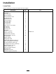
Installation Loose Parts Use the chart below to verify that all parts have been shipped.
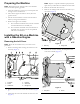
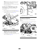
Preparing the Machine Note: Prepare to capture and clean up any fuel that spills when you disconnect the fuel line from the tank. Note: Determine the left and right sides of the machine from the normal operating position. 4. Remove the fuel tank from the tray. 5. Remove the 2 flange bolts that secure the tank tray to the frame (Figure 2). 1. Move the machine to an area in your work space with enough room to install the kit. 2. Shut off the engine and remove the key from the ignition switch. 3.
Removing the Right Cover Removing the Left Hip Restraint Note: Retain all the hardware that you remove in this procedure. Remove and retain the 3 flange bolts and flange nuts that secure the hip restraint to the machine (Figure 6). 1. Remove the negative (–) cable from the battery and then the positive (+) cable. Figure 6 Figure 4 1. Nut 2. Positive cable (+) 1. Hip restraint (short) 3. Flange nut (5/16 inch) 2. Flange bolt (5/16 x 3/4 inch) 3. Bolt 4. Negative cable (–) 2.
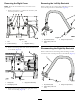
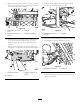
Disconnecting the Parking-Brake Cables 1. Loosen the jam nut and then turn the adjustment screw 2 turns counter clockwise on both rear-brake calipers (Figure 8). Figure 10 1. Shift cable Note: Mark each end of the cable to identify the front and rear cable ends. Use this as a reference when you install the new shift cable. 5. Disconnect the choke cable from the engine (Figure 11). Figure 8 1. Adjustment screw 3. Brake cable 2. Jam nut 2.
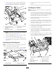
Note: Remove the cable ties that prevent you from partially removing the dashboard. You will need to replace the cable ties in a later step. 7. Remove the retaining nut on the choke cable and pull it through the dashboard. Installing the TOR-6040 Support Kit Use the TOR-6040 support kit when you install the multi-passenger kit. 1. Remove flange bolt on the throttle bracket (Figure 13). 2. Use the 2 flange nuts, washer, and thread rod to install the bridge support to the engine (Figure 13). Figure 14 1.
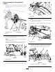
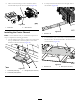
2. Remove the flange bolts (3/8 x 2-1/2 inches) and nuts that secure the side rail to the machine (Figure 16). Do this on both sides of the machine. 5. Remove the self-tapping screw that secures the tee fitting to the center channel (Figure 18). Figure 16 1. Flange bolt (5/16 x 3/4 inch) 3. Side rail 2. Flange bolt (3/8 x 2-1/2 inches) 4. Flange nut (3/8 inch) Figure 18 1. Self-tapping screw (1/4 x 3/4 inch) 2. Tee fitting 6.
. Have an assistant help you move the front section forward and away from the rear section (Figure 20). 2. Loosely install the extension rail to the right side of the machine (Figure 22). Figure 20 1. Brake line 2. Wire harness Figure 22 Installing the Center Channel 1. Extension rail Note: Use the hardware that you retained from a previous step to complete the following procedure. 3.
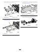
4. Insert the 2 bolts (3/8 x 3/4 inches) through the center channel and rear mount (Figure 24). 6. Use the 2 bolts (5/16 x 3/4 inch) to loosely install the extension rail to the center channel to the front section of the machine (Figure 26). Figure 26 1. Bolts (5/16 x 3/4 inch) Figure 24 1. Channel extension 2. Extension rail 7. Have an assistant help you bring the front and rear sections of the machine together (Figure 27). 2. Bolt (3/8 x 3/4 inch) 5.
8. Use the 3 bolts (3/8 x 2-1/2 inches) and flange nuts to loosely install the extension rail to the rear frame (Figure 28). Do this on both sides of the machine. 2. Perform the previous step to the other side of the machine. 3. Remove the engine and leg supports from the machine. Installing the Cables Note: Exit the cables and wire harness on the right side of the center channel. 1.
Adjusting the Throttle Cable 7. Install the remaining channel hardware (Figure 31). 1. Use the jam nuts on the cable to adjust and secure the cable to the bracket (Figure 33). Figure 31 1. Bolt (5/16 x 3/4 inch) 2. Center channel 8. Replace any cable ties that you removed to access the area under the dashboard. Figure 33 9. Use the 10 screws (1/4 x 1-1/4 inches) to secure the dashboard to the machine (Figure 32). 1. Throttle-cable bracket 3. Jam nut (2) 2. Throttle cable 4. Throttle assembly 2.
Installing the Floor Plate Adjusting the Shift Cable Use the 4 flange bolt (5/16 x 1-1/4 inches), 4 bolt (1/4 x 1-1/4 inches), and locknuts to secure the rear floor plate to the machine (Figure 36). 1. Set the shift lever to the middle position. 2. Thread the ball-joint assembly onto the shift cable and secure it to the shift-arm assembly (Figure 35). Figure 35 1. Ball-joint assembly 4. Jam nut 2. Shift-arm assembly 5. Jam nuts 3. Shift-cable bracket 6. Shift cable Figure 36 3.
2. Use the 2 bolts (3/8 x 2-1/2 inches) and flange nuts to secure the seat supports on the rear section of the machine (Figure 38). Figure 40 1. Screw (#10 x 1/2 inch) 2. Bolt with washer assembly 4. Angled-support bracket (1/4 x 1/2 inch) Figure 38 1. Flange nut (3/8 inch) 3. Seat-base panel 3. Flange bolt (3/8 x 2-1/2 inches) 5. Use the 5 screws (#10 x 1/2 inch) to secure the back panel to the seat brace and the seat supports (Figure 40). 2. Seat support 3.
2. Use the 3 self-tapping screws to secure the opening cover to the side plate (Figure 44). Figure 44 1. Opening cover 3. Use the hardware you removed earlier to install the original right panel assembly to the rear seat-base panels (Figure 45). Figure 42 1. Seat-base panel 4. Support bracket 2. Screw (#10 x 1/2 inch) 5. Panel bracket 2. Self-tapping screw 3. Bolt with washer assembly 8.
Figure 48 1. Nut 2. Positive cable 2. Use the bolt and nut to secure the negative (–) cable to the battery terminal (Figure 48). Figure 46 1. Left panel assembly 3. Bolt 4. Negative cable 2. Self-tapping screw Connecting the Fuel Tank 1. Place the fuel tank on the tank tray (Figure 49). Figure 47 1. Tank tray Figure 49 2. Flange bolt 1. Fuel tank 2. Screw 3. Hold-down Connecting the Battery 1. Use the bolt and nut to secure the positive (+) cable to the battery terminal (Figure 48). 4.
Securing the Hip Restraint Installing the Seat Assembly 1. Use the flange bolt (3/16 x 3/4 inch) and flange nut that you removed earlier to secure the right, rear-hip restraint to the rear seat base (Figure 50). 1. Contact your Toro dealer to obtain an additional seat assembly. 2. Install the original seat assembly to the rear seat row (Figure 52). Figure 52 Figure 50 1. Flange bolt (3/16 x 3/4 inch) 1. Original seat assembly 2. Additional seat assembly (bucket seat version shown) 2. Flange nut 3.
Installing the Kit on a Machine with an Electric Motor 4. Remove the 2 bolts securing the charger bracket to the battery tray (Figure 55). Removing the Side Covers 1. Remove the front flange bolt and flange nut on the right hip restraint (Figure 53). Figure 55 1. Side-cover assembly 2. Self-tapping screw Figure 53 1. Flange bolt (3/16 x 3/4 inch) 3. Bolt 2. Flange nut 5. Remove the 4 self-tapping screws securing the left side cover to the machine (Figure 55). 2.
2. Disconnect the watering hose from the batteries in the front battery tray (Figure 56). Figure 57 1. Positive (+) terminal 2. Negative (–) terminal 3. Disconnect the battery cables connected to the positive (+) terminal on the batteries in the front battery tray (Figure 57). 4. Disconnect the battery cables connected to the negative (–) terminal on the batteries in the front battery tray (Figure 57).
Disconnecting the Parking-Brake Cable 5. Remove the 2 screws and nuts that secure the fuse block to the front battery tray. 1. Loosen the jam nut and then turn the adjustment screw 2 turns counter clockwise on both rear-brake calipers (Figure 60). Figure 58 1. Screw (#10 x 3/4 inch) 3. Fuse block 2. Nut (#10) Figure 60 1. Adjustment screw 6. Remove the 4 bolts securing the battery tray to the machine (Figure 59). 3. Brake cable 2. Jam nut 2.
Separating the Machine Note: Retain all the hardware that you remove in this procedure. 1. Install the support leg to the machine (Figure 62). Figure 64 3. Side rail 2. Flange bolt (5/16 x 3/4 inch) 4. Flange nut (3/8 inch) 4. Working from front to back, remove the flange bolts (5/16 x 3/4 inch) that secure the side rail to the machine (Figure 64). Do this on both sides of the machine. Figure 62 1. Flange bolt (3/8 x 1 inch) 1. Flange bolt (3/8 x 2-1/2 inches) 5.
Figure 68 1. Brake line 2. Wire harness Figure 66 1. Self-tapping screw (1/4 x 3/4 inch) Installing the Center Channel 2. Tee fitting Note: Use the hardware that you removed earlier to complete the following procedure. 7. Remove the bolts and flange nuts that secure the swing arm mount to the center channel (Figure 67). 1. Use the 4 flange bolts (3/8 x 3/4 inch) to loosely install the top and bottom connection plates to the center channel on the front section (Figure 69). Figure 69 Figure 67 1.
Figure 70 Figure 72 1. Extension rail 1. Channel extension 3. Use the 2 bolts (5/16 x 3/4 inch) to loosely install the extension rail to the center channel to the front section of the machine (Figure 71). 5. Loosely install the extension rail to the left side of the machine (Figure 73). Figure 71 1. Extension rail 2. Bolt (3/8 x 3/4 inch) Figure 73 2. Bolts (5/16 x 3/4 inch) 1. Extension rail 4.
Installing the Side Supports 7. Have an assistant to help you bring the front and rear sections of the machine together (Figure 75). Note: Use the bolts and nuts that you removed in the previous sections to complete the following procedure. 1. Use the 4 bolts (5/16 x 3/4 inch) to loosely install the platform support to the center channel (Figure 77). Figure 75 8. Use the 3 bolts (3/8 x 2-1/2 inches) and flange nuts to loosely install the extension rail to the rear frame (Figure 76).
Installing the Cables Note: Exit the cables and wire harness on the right side of the center channel. 1. Connect the parking-brake cable to the parking-brake lever in the front section of the machine, run it through the center channel, and connect it to the parking-brake assembly in the rear section of the machine. 2. Loosely install the 2 bolts (3/8 x 3/4 inch), 16 bolts (1/4 x 1/2 inch), and 2 flange nuts (3/8 inch) to secure the bottom plate to the center channel (Figure 78). Figure 80 1.
Installing the Rear Seat Base 4. Use the flange bolt (3/8 x 2-1/2 inches) and flange nut to secure the seat support (Figure 84). 1. Use the 2 flange nuts and bolts to secure the rear and front battery trays together (Figure 82). Figure 82 1. Bolt 3. Bolt (3/8 x 3/4 inch) 2. Flange nut (3/8 inch) 2. Use the 4 bolts (3/8 x 1 inch) to secure the front battery tray to the machine (Figure 82). 3. Use the 2 screws and nuts that secure the fuse block to the front battery tray (Figure 83). Figure 84 1.
7. Use the 2 bolts (1/4 x 2 inches), washer, and locknut to secure the left and right panel bracket the machine (Figure 86). 5. Use the 2 bolt with washer assemblies (1/4 x 1/2 inch) to secure the angled-support bracket and seat-base panel to the left and right seat supports (Figure 85). Figure 86 Figure 85 Some parts are hidden for illustrative purposes. 1. Screw (#10 x 1/2 inch) 1. Bolt (1/4 x 2 inches) 3. Panel bracket 2. Washer 4. Locknut (1/4 inch) 8.
10. Use the 4 self-tapping screws to secure the right side cover to the seat assembly (Figure 88). 12. Use the 3 flange bolt (3/16 x 3/4 inch) and flange nuts that you removed earlier to secure the left rear-hip restraint to the seat base assembly (Figure 90). Figure 90 3. Flange nut 1. Hip restraint (tall) 2. Flange bolt (3/16 x 3/4 inch) Figure 88 1. Side-cover assembly 2. Self-tapping screw Installing the Front Seat Base 11.
Figure 92 1. Seat support 3. Spacer 2. Flange bolt (3/8 x 2-1/2 inches) 4. Flange nut (3/8 inch) Figure 94 1. Side-cover assembly 3. Use the 2 bolt with washer assemblies (1/4 x 1/2 inch) to secure the angled-support bracket and seat-base panel to the left and right seat supports (Figure 93). 2. Self-tapping screw 6. Use the 3 self-tapping screws to secure the opening cover to the side plate (Figure 95). Figure 95 1. Opening cover 7.
Figure 96 1. Hip restraint (short) 3. Hip restraint (tall) 2. Flange bolt (3/16 x 3/4 inch) 4. Flange nut Installing the Batteries 1. Install the 4 batteries into the front battery tray (Figure 97). Figure 97 1. Hold-down rod 2. Washer 5. Hold down 6. Watering house 3. Battery 7. Battery cable 4. Locknut 2. Use the hold-down rod, washer, hold down, and locknut to secure the batteries to the battery tray (Figure 97).
3. Connect the battery cables to the positive (+) terminal to the batteries (Figure 97). Figure 98 1. Positive terminal (+) 2. Negative terminal (–) 4. Connect the battery cables connected to the positive (+) terminal on the batteries in the front battery tray (Figure 98). 5. Connect the battery cables connected to the negative (–) terminal on the batteries in the front battery tray (Figure 98). 6. Install the watering house to the batteries (Figure 97). Installing the Seat Assembly Figure 99 1.
Notes: 31