
Operator's Manual
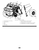

Setup
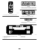
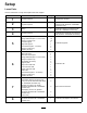
LooseParts
Usethechartbelowtoverifythatallpartshavebeenshipped.
ProcedureDescription
Qty.
Use
1
Nopartsrequired
–
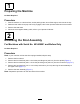
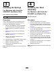
Preparethemachine.
2
Nopartsrequired
–
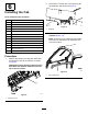
Removethestrutassembly(for
machineswithSerialNo.403448001
andbeforeonly).
3
Spring
2
Installthesprings(formachineswith
SerialNo.403448001andbefore).
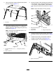
4
Nopartsrequired
–
Installthestrutassembly(formachines
withSerialNo.403448001andbefore).
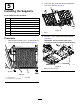
Floor-platesupport2
Flange-headbolt(5/16x1-1/4inches)
16
Flangenut(5/16inch)
16
Leftcabsupport
1
Rightcabsupport1
Hex-headbolt(3/8x1-1/4inch)
4
Flangenut(3/8inch)
4
5
Washer(3/8inch)
4
Installthesupports.
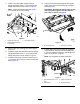
Cabframe
1
Backfoamseal
1
Backfoamsealcarpet
1
Flange-headbolt(5/16x1-1/4inches)
4
Flangenut(5/16inch)
4
Flatwasher(5/16inch)
4
Supportplate
2
Right,frontfoamseal
1
Left,frontfoamseal
1
Upper,rearfoamseal
1
Foamseal2
Hex-headbolt(3/8x1-1/4inches)
6
Flangenut(3/8inch)
6
6
Washer(3/8inch)
6
Installthecab.
Fuseblock1
Hex-washerheadscrew(#10x3/4
inch)—forelectricmachineswithSerial
No.403448001andafteronly
2
Serratednut(#10)—forelectric
machineswithSerialNo.403448001
andafteronly
2
Self-tappingscrew—forgasoline
machineswithSerialNo.403448001
andafteronly
2
7
Fuse(15A)
1
Routethewireharness.
8
Cabadapterwireharness—forelectric
machineswithSerialNo.403448001
andafteronly.
1Installthecabadapterwireharness.
3