
Operator's Manual
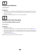
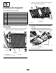
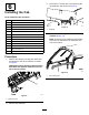

4.Installanewoor-platesupportusing8
ange-headbolts(5/16x1-1/4inches)and8
angenuts(5/16inch)asshowninFigure5.
Note:Torquetheange-headbolts(5/16x
1-1/4inches)to34N∙m(25ft-lb).
g035247
Figure5
1.Flangenut(5/16inch)
3.Floor-platesupport
2.Flange-headbolt(5/16x
1-1/4inches)
5.Removetheotherexistingoor-platesupport
(Figure4).
6.Installtheothernewoor-platesupportusing8
ange-headbolts(5/16x1-1/4inches)and8
angenuts(5/16inch)asshowninFigure5.
7.Installthepreviouslyremoved4screws(1/4x
1-1/4inches)and4nuts(1/4inch)intotheoor
plate(Figure2).
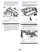
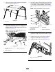
8.Usingthenewoor-platesupportsasaguide,
drill3holes(3/8-inchdiameter)intoeachoor
plate(Figure6).
Important:Drillonlythefront2holesonthe
newoor-platesupportsandthefarthest,
rearhole;asshowninFigure6.
g038352
Figure6
1.Donotdrillthishole.
2.Frontofthemachine
9.Looselyattachtheleftandrightcabsupports
tothemachineusingthehex-headbolts(3/8x
1-1/4inch),washers(3/8inch),andangenuts
(3/8inch)asshowninFigure7.
Note:Donottightentheboltsatthistime.
g037135
Figure7
1.Hex-headbolt(3/8x1-1/4
inch)
3.Flangenut(3/8inch)
2.Cabsupport4.Washer(3/8inch)
8