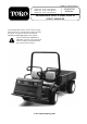
FORM NO. 3318-415 GB Rev A MODEL NO. 07205—60001 AND UP MODEL NO. 07206—60001 AND UP MODEL NO. 07215—60001 AND UP ® OPERATOR MANUAL WORKMAN 3300-D AND 4300-D UTILITY VEHICLES To understand this product, and for safety and optimum performance, read this manual before starting the engine. Pay special attention to SAFETY INSTRUCTIONS highlighted by this symbol. It means CAUTION, WARNING or DANGER—personal safety instruction. Failure to comply with the instruction may result in personal injury.
Foreword The TORO WORKMAN® was developed to provide an efficient, versatile, trouble free and economical work vehicle. The latest concepts of engineering, design and safety have been incorporated into this machine, along with the highest quality parts and workmanship. Excellent service will be derived if proper operation and maintenance practices are followed. This vehicle is not designed or manufactured for use on roads, streets or highways. It is not appropriate for such use.
Safety The WORKMAN® was designed and tested to offer safe service when operated and maintained properly. Although hazard control and accident prevention partially are dependent upon the design and configuration of the machine, these factors are also dependent upon the awareness, concern, and proper training of the personnel involved in the operation, maintenance and storage of the machine. Improper use or maintenance of the machine can result in injury or death.
Safety 13. Since gasoline is highly flammable, handle it carefully. A. Sit on operator’s seat and engage the parking brake. A. Use an approved gasoline container. B. Disengage PTO (if so equipped) and return the hand throttle lever to OFF position (if so equipped). B. Do not remove cap from fuel tank when engine is hot or running. C. Do not smoke while handling gasoline. D. Fill fuel tank outdoors and to about one inch below top of tank (bottom of filler neck). Do not overfill. E.
Safety F. Avoid sudden stops and starts. Do not go from reverse to forward or forward to reverse without first coming to a complete stop. 21. Before getting off the seat: A. Stop movement of the machine. B. Lower bed. G. Do not attempt sharp turns or abrupt maneuvers or other unsafe driving actions that may cause a loss of vehicle control. H. When dumping, do not let anyone stand behind vehicle and do not dump load on any one’s feet. Release tailgate latches from side of box, not from behind. C.
Safety tion, keep all nuts, bolts and screws properly tightened. 28. To reduce potential fire hazard, keep the engine area free of excessive grease, grass, leaves and accumulation of dirt. 29. If the engine must be running to perform a maintenance adjustment, keep hands, feet, clothing, and any parts of the body away from the engine and any moving parts. Keep everyone away. 30. Do not overspeed engine by changing governor settings. Maximum engine speed is 3650 rpm.
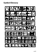
Symbol Glossary SAFETY ALERT SYMBOL GENERAL HAZARD SAFETY ALERT CRUSHING OF WHOLE BODY, APPLIED FROM ABOVE CRUSHING OF TOES OR FOOT, CRUSHING OF FINGERS OR HAND, CUTTING OF FINGERS OR HAND CUTTING OF FOOT FORCE APPLIED FROM ABOVE FORCE APPLIED FROM SIDE KEEP CHILDREN A SAFE DISTANCE FROM BATTERY STAY A SAFE DISTANCE FROM MACHINE STAY A SAFE DISTANCE FROM DRAINING STAY A SAFE DISTANCE FROM MACHINE STAY A SAFE DISTANCE FROM TANK HYDRAULIC OIL VALVE EXPLOSION FIRE OR OPEN FLAME FIRE, OPEN LIGHT & SMOK
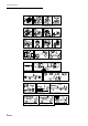
Symbols Glossary THROWN OR FLYING OBJECTS, SEVERING OF FINGERS OR FACE EXPOSURE HAND, ENGINE FAN RIDING ON THIS MACHINE IS SHUT OFF ENGINE & REMOVE ALLOWED ONLY ON A PASS- KEY BEFORE PERFORMING ENGER SEAT & ONLY IF THE MAINTENANCE OR REPAIR WORK DRIVER'S VIEW IS NOT HINDERED MACHINE TIPPING USE CAUTION ON STEEP HILLS MACHINE TIPPING MACHINE TIPPING DO NOT JUMP FROM TIPPING MACHINE HOLD TIGHTL & BRACE FEET HOLD HIP RESTRAINT & HAND HOLD, BRACE FEET LEAN AWAY FROM TIP STAY CLEAR OF ARTICULATION RUNO
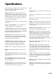
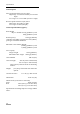
Specifications Type: 4-wheel step-through, out-front operator style, two-person vehicle. Certified to meet ANSI Specifications B56.8-1988. Engine: Mitsubishi three-cylinder, liquid-cooled, counterbalanced, diesel engine. Rated at 17 kW (23 hp), governed to a maximum speed of 3650 rpm by a mechanical governor. 952 cc (58 cu. in.) displacement. Forced lubrication by gear pump. 12 volt electric starter. Spin-on oil filter. Air Cleaner: Heavy duty, 2-stage, remote mounted air cleaner.
Specifications Ground Speed: Forward Speeds with 61 cm (24”) TiresHigh range: 12.2/18.5.9/1.9 kmh (7.6/11.5/19.8 mph) Low range: 4.7/7.2/12.4 kmh (2.9/4.5/7.7 mph) Reverse Speeds with 61 cm (24”) TiresHigh range: 11.6 kmh (7.2 mph) Low range: 4.5 kmh (2.8 mph) General Specifications (approx.): Base Weight: Dry w/o flatbed 522.5 kg (1400 lbs.) 2-wd 597kg (1600 lbs.) 4-wd Rated Capacity: 970 kg*(2,600 lbs) *includes 74.6 (200 lb.) operator and 74.6 (200 lb.) passenger and loaded attachment. Maximum.
Before Operating CHECK CRANKCASE OIL The engine is shipped with oil in the crankcase; however, the level of oil must be checked before and after the engine is first started. CAUTION Before servicing or making adjustments to the machine, stop the engine, set the parking brake and the remove key from the switch. Any load material must be removed from the bed or other attachment before working under the raised bed. Always rotate the safety support to the down position before working under the raised bed.
Before Operating Check the level of coolant at beginning of each day before starting the engine. ➀ 1. Park the machine on a level surface. 2. Check coolant level. Coolant should be up to the COLD line on the reserve tank when the engine is cold. CAUTION Figure 3 1. Fuel tank cap 4. Wipe up any fuel that may have spilled to prevent a fire hazard. If the engine has been running, pressurized hot coolant can escape if radiator cap is removed and cause burns.
Before Operating 2. Clean the area around the dipstick. 3. Unscrew the dipstick from the top of the transaxle and wipe it with a clean cloth. ➀ Figure 6 1. Front differential 2. Fill plug 3. Drain plug Figure 5 1. Dipstick 4. Screw the dipstick into the transaxle and make sure it is seated fully. Unscrew the dipstick and check fluid level. Fluid should be up to the top of flat portion of the dipstick. If the level is low, add enough fluid to achieve the proper level.
lowing charts to determine correct tire pressures for tire size and payload of vehicle. CHECK BRAKE FLUID The brake fluid reservoir is shipped from the factory filled with brake fluid. Check the level before the engine is first started and every 8 hours or daily, thereafter. 1. Park the machine on a level surface. 2. Fluid level should be up to the FULL line on reservoir.
Controls Accelerator Pedal (Fig. 8)—Used to vary engine and ground speed when the transmission is in gear. Depressing the pedal increases engine RPM and ground speed. Releasing it will decrease engine RPM and ground speed. ➀ Shift Pattern R 2 1 3 IMPORTANT: Do not shift the transaxle to the reverse or forward gear unless the vehicle is standing still. Damage to the transaxle may occur. ➁ ➂ Figure 8 1. Accelerator pedal 2. Clutch pedal 3. Brake pedal Clutch Pedal (Fig.
Controls of wheels. the passenger seat. Hydraulic Lift (Fig. 9)—Raises and lowers bed. Move rearward to raise, forward to lower. High-Low Range Shifter (Fig. 9)—Adds three additional speeds for precise speed control. 8 A. The vehicle must be completely stopped before shifting between High and Low range. 2 7 5 B. 3 6 1 Shift only on level ground. C. Depress the clutch pedal fully. 4 D. Move the lever fully forward for High and fully rearward for Low. Figure 9 1. Gear shift lever 2.
Controls To check warning light operation: ➄ ➀ 1. Apply the parking brake. ➅ ➇ ➃ ➁ ➆ ➂ Figure 10 1. Tilt steering lever 2. Ignition switch 3. Horn button 4. Coolant temp. gauge 5. Engine low oil pressure light 6. Charge indicator 7. Glow plug switch 8. Glow plug indicator 2. Turn the ignition key to “ON”, but do not start the engine. The charge indicator and oil pressure lights should glow.
Controls Tachometer (optional-not shown)—Indicates engine RPM. Gear selection graphics indicate speed. Remote Hydraulic Lever (optional-not shown)— Controls hydraulic flow to optional quick rear couplers.
Operating PRE-STARTING CHECKS arator serviced, etc. Safe operation begins before taking the vehicle out for a day’s work. You should check these items each time: Refer to Bleeding The Fuel System. 1. Check tire pressure. 2. Disengage the PTO Power Take Off (if so equipped) and return the hand throttle lever to the OFF position (if so equipped). Note: These tires are different than car tires, they require less pressure to minimize turf compaction and damage. 2.
Operating ➁ ➀ Figure 12 1. Fuel filter/water separator 2. Air bleeder screw 3. Open the air bleed screw on the fuel injection pump (Fig. 13) with a 10-mm wrench. 4. Turn the ignition key to ON. The electric fuel pump will begin operation, forcing air out around air bleed screw on fuel injection pump. Leave the key in the ON position until a solid stream of fuel flows out around the screw. Tighten the screw and turn the key to OFF.
Operating NEW VEHICLE BREAK-IN depressed or PTO (if so equipped) is disengaged. Your Workman is ready for work. To provide top performance and long vehicle life, follow these guidelines for the first 100 operating hours. To verify the clutch interlock switch operation: • • Check the fluid and engine oil levels regularly and be alert for indications of overheating in any part of the vehicle. After starting a cold engine, let it warm up for about 15 seconds before shifting into gear.
Operating Many factors contribute to accidents. You have control over several of the most important. Your actions, such as driving too fast for conditions, braking too fast, turning too sharp, and combinations of these, are frequent causes of accidents. SPEED One of the major causes of accidents is fatigue. Be sure to take occasional breaks. It is important that you stay alert at all times. Speed can also make a minor accident worse.
Operating ability to stop and/or turn. Heavier loads and heavier attachments make a vehicle harder to stop or turn. The heavier the load, the longer it takes to stop. The braking characteristics also change with no bed or attachment on the vehicle. Fast stops may cause the rear wheels to lock up before the front wheels lock up, which may affect the control of the vehicle. It is a good idea to decrease vehicle speed with no bed or attachment. Turf and pavement are much slipperier when they are wet.
Operating In case of tipover Don’t jump Tipover can occur if the truck is improperly operated. Injury or death could result. down the hill more safely. Reduce the weight of the load if it is a steep hill or if the load has high center of gravity. Remember, loads can shift. Secure them. Operator: Hold tight and brace feet. Passenger: Hold hip restraint and hand hold, brace feet Note: The Workmen have excellent hill climbing ability. The differential lock will increase this ability.
Operating in various combinations that allow for maximum capacity and versatility. The full-sized box is 1.4m wide by 1.64 m long and can hold up to 900 kg of evenly distributed cargo. Loads vary in how they are distributed. Sand spreads out evenly and quite low. Other items, such as bricks, fertilizer or landscape timbers, stack higher in the box. WARNING The bed will lower whenever the dump lever is pushed down, even when the engine is off. Turning off the engine will NOT prevent the box from lowering.
Operating WARNING Tipping or rolling the vehicle on a hill will cause serious injury. • The extra traction available with the differential lock can be enough to get you into dangerous situations such as climbing slopes that are too steep to turn around. Be extra careful when operating with the differential lock on, especially on steeper slopes.
Operating Instructions When equipped with a tow hitch bolted onto rear axle tube, your Workman can tow trailers or attachments with a Gross Trailer Weight (GTW) up to 680 kg. Always load a trailer with 60% of the cargo weight in the front of the trailer. This places approximately 10% (90 kg max.) of the Gross Trailer Weight (GTW) on the tow hitch of the vehicle.
Maintenance Daily Maintenance Procedures Check the following items daily • Safety Interlock operation • Service & park brake operation • Fuel level • Accelerator operation • Clutch & shifter operation • Engine oil level • Transaxle oil level • Cooling system fluid level • Brake fluid level • Air cleaner (dust cup & baffle)(more often when conditions are dirty), • Unusual engine noises • Tire pressure • Radiator screen/cleanout door • Hydraulic hoses for damage • Fluid leaks •
Maintenance WORKMAN 4300-D QUICK REFERENCE AID Check/Service 1. Engine oil level 2. Engine oil drain 3. Transaxle/Hydraulic oil level (dipstick) front 4. Belts (Governor, water pump hydraulic pump) 5. Coolant level fill 6. Fuel 7. Grease points (37) 100 hours 8. Radiator screen 8.1 Radiator cleanout door 9. Air filter 10. 11. 12. 13. 14. 15. 16. 17.
Maintenance Maintenance Schedule Minimum Recommended Maintenance Intervals Maintenance Procedure Check battery fluid level/ Every 50 cable connections hours ‡Change engine oil and filter Maintenance Interval& Service Every 100 hours Every 200 hours Every 400 hours Every 800 hours Lubricate all grease fittings Inspect the condition and wear of the tires ✝Change engine oil and filter Inspect cooling system hoses ✝Check cable adjustments ✝Check alternator and fan belts Service the air filter Check fron
Maintenance GREASING BEARINGS AND BUSHINGS WARNING Before servicing or making adjustments to the machine, stop the engine, set the parking brake and remove key from the ignition switch. Any load material must be removed from bed or other attachment before working under raised bed. Never work under a raised bed without positioning safety support on a fully installed cylinder rod. Always rotate the safety support to the down position before working under the raised bed.
Maintenance Figure 19 Figure 21 Figure 20 Figure 22 IMPORTANT • After extended operation in mud, sand, water or similar dirty conditions, have your brakes inspected and cleaned and drive axle joints greased as soon as possible. This will prevent any abrasive material from causing excessive wear. • Under frequent heavy duty operating conditions, lubricate all grease fittings and inspect air cleaner daily to prevent excessive wear.
Maintenance CAUTION Only qualified and authorized personnel shall be permitted to maintain, repair, adjust or inspect the vehicle. Avoid fire hazards and have fire protection equipment present in the work area. Do not use an open flame to check the level or leakage of fuel, battery electrolyte or coolant. Do not use open pans of fuel or flammable cleaning fluids for cleaning rest support channel. 5. Always install or remove bed support from outside of bed. 6.
Maintenance 3. The jacking point at the front of the vehicle is under the front center frame support and at the rear it is under the axle tube. 4. When jacking up front of the vehicle, always place a 50 x 100mm block (or similar material) between the jack and vehicle frame. ➀ Figure 25 1. Front jacking point ➀ ➀ Figure 26 1.
Maintenance Locations For Selected Maintenance Procedures ➀ ➁ Figure 30 1. Fuel filter/water Separator 2. Fuel pump Figure 27 1. Dust Cup & Baffle 2. Filter Element 3. Air Cleaner Body ➀ Figure 31 ➀ 1. Drain Plug 2. Filter Canister Figure 28 1. Engine Oil Drain Plug ➀ Figure 32 Figure 29 1. Engine Oil Filter 1. Fuel pump cover 2. Filter 3.
Maintenance ➀ ➀ ➁ ➁ Figure 36 Figure 33 1. Hydraulic Filter 2. Gasket 1. Radiator screen cover 2. Clean out door ➁ ➀ Figure 37 Figure 34 1. Front differential 2. Fill/check plug 3. Drain plug 1. Radiator cap 2. Reserve tank cap ➀ ➁ Figure 38 Figure 35 1. Hydraulic Reservoir 2 Drain plug 36 1.
Maintenance FRONT WHEEL TOE-IN After every 400 operating hours or annually, check front wheel toe-in. 1. Measure center-to-center distance (at axle height) at front and rear of steering tires. Front measurement must be equal to the rear measurement 3mm. EMERGENCY BOX RAISING (without starting the engine) The box can be raised in an emergency by cranking starter and holding lift lever. Run starter for 15 seconds then wait 60 seconds before engaging starter again.
Maintenance JUMP STARTING PROCEDURE 1. Loosen knobs securing battery cover to battery base and slide cover off. 2. Connect a jumper cable between the positive posts of the two batteries. The positive post may be identified by a “+” sign on top of battery cover. WARNING Jump starting can be dangerous. To avoid personal injury or damage to electrical components in the vehicle, observe the following warnings: • • Never jump start with a voltage sources greater than 15 volts D.C.