MODEL NO. 07205 — 70001 & Up MODEL NO. 07205 TC ~ 70001 & Up MODEL NO. 07206 TC — 70001 & Up MODEL NO. 07215 — 70001 & Up MODEL NO. 07215 TC ~ 70001 & Up To assure maximum safety, optimum performance, and o gain knowledge of the product, it is essential that you or any other operator of the machine read and understand the contents of this manual before the engine is ever started.
FOREWORD The TOR WORKMAN® was developed to provide an efficient, versatile, trouble free and economical work vehicle. The latest concepts of engineering, design and safety have been incorporated into this machine, along with the highest quality parts and workmanship. Excellent service will be derived if proper operation and maintenance practices are followed. A WARNING The WORKMAN® is an off-highway vehicle only, and is not designed, equipped, or manufactured for use on public streets, roads or highways.
FOREWORD The TOR WORKMAN® nests the requirements of ANSI Supervisors, operators and service persons should be familiar with the following standards and publications: {The material may be obtained from the address showroom. s Flammable and Combustible Liquids Code: EXPANSION 30 e National Fire Protection Association: EXPANSION #505; Powered Industrial Trucks ADDRESS: National Fire Prevention Association Barry march Park Quincy, Massachusetts 02269 U.S.A * CLANSMEN B56.
TABLE OF CONTENTS SAFETY INSTRUCTIONS SAFETY AND INSTRUCTION DECALS SPECIFICATIONS LOOSE PARTS CHART INSTRUCTIONS Install Rear Fenders . Install Wheels .. .. i Install Steering Wheel . 13 install Front Fenders .. 14 install Seat Frame .. .. .14 Install Seat Back Cushions, Manual Tube and Bed Safety Support 14 Install TOPS 15 Activate and Charge Battery BEFORE OPERATING Check Crankcase Oil Fill Fug Tank Check Cooling System . . Check Trans axle { Hydraulic Fluid .
A SAFETY INSTRUCTIONS The WORKMAN® was designed and tested 1o offer safe. service _when operated _and maintained properly. Although hazard control and accident prevention partially are dependent upon the design and configuration of the machine, these factors are also dependent upon the awareness, concern, and proper training of the personnel involved in the operation, maintenance and storage of the machine. Improper use or maintenance of the machine can result in injury or death.
A SAFETY INSTRUCTIONS 17. When starting the engine: A. Sit on operator’s seat and engage parking brake. B. Disengage any attachments and return hand throttle lever to OFF position (i so equipped). C. Move shift Ever to NEUTRAL and depress clutch peat. D. Keep foot off accelerator pedal. E. Turn ignition key to ON, hold glow plug switch ON. (Maximum 30 seconds) F Turn ignition key to START. 18. Using the machine demands attention.
A SAFETY INSTRUCTIONS 26. Before disconnecting or performing any quark on the hydraulic system, all pressure in system must be relieved by stopping engine, cycling dump valve from raise to lower and/or lowering box and attachments. Place the remote hydraulics lever in the float position. if box must be in raised position, secure with safety support. 27. To make sure entire machine is in good condition, keep all nuts, obits and screws properly tightened. 28.
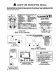
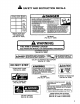
A SAFETY AND INSTRUCTION DECALS The following safety and instruction decals are installed on the machine. If any become damaged or illegible, replace them. Decal part numbers are listed below and in the parts catalog. Order replacements from your Authorized TOR Distributor. WORKMAN 4300-D QUICK REFERENCE AID SERVICEABLE 10, EEL PP 1-ENGINE OL LEVEL 11, BATTERY 16 2 ENGINE O DARN 12, TIRE PRESSURE MAXIMUM 20 P51 *LIBELOUS oY . T Russ L AN notch s T CINDERELLA |, MRS HYDRAULIC O FILTER {Part No.
A SAFETY AND INSTRUCTION DECALS UNDER DASH NEXT TO FUSE BLOCK {Part No. B-6670) E DIFFERENTIAL LOCK WHEN TURNING. ~ AVOID ENSURE SHARP TURNS, STARTS AlD STOPS AVOID HOLES, DADO OFFS, ~REDUCE SPEED Wit H HEAVIER LOADS. A WARNING THIS ARM IS SPRING LOADED! SEE OPERATORS MANUAL FOR DISASSEMBLY PROCEDURE DANGER FAILURE 70 COMPLY WITH THE FOLLOWING SAFETY REQUIREMENTS WAY RESULT [¥ PERSONAL INJURY OR AHEAD AND UNDERSTAND OPERATORS !MANUAL BEFORE OPERATING THIS MACHINE. VEHICLE iS FOR OFF ROAD USE ONLY.
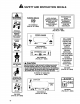
A SAFETY AND INSTRUCTION DECALS WARNING =l TIP OVER CAN OCCUR IF TRUCK 18 {PROPERLY OPERATED, JURY OR DEATH COULD RESULT ENCASE OF TIP OVER LEa DON'T Jump 3 OPERATOR HOLD TIGHT AND BRACE & PASSENGER HOLD HIP RESTRAINT AND HAND HOLD. BRACE & LEAN AWAY 875980 ON TOPS (Part No. 87—5980) TRANSMISSION PARKING BRAKE HITCH RATING: FLUID MAXIMUM TONGUE || USE DETHRONE Il ® WEIGHT 200 LBS. AUTOMATIC 51 onion MAXIMUM TRANSMISSION TRAILER WEIGHT; FLUID OR ON CONSOLE ; (Part No. 87 —8020) 1500 LBS.
SPECIFICATIONS Type: 4 wheel step through, out front operator style, . meet. ANSI Specifications B56.8a— 1994, Engine: Mitsubishi three cylinder, liquid cooled, counterbalanced, dies! engine. Rated at 23 hp, governed to a maximum speed of 3650 rpm by a mechanical governor. 58 cu. in. (852 cc) displace merit. Forced lubrication by gear pump. 12 volt electric starter. Spin-on oil filter. Air Cleaner: Heavy duty, 2-stage, remote mounted air cleaner.
LOOSE PARTS CHART Note: Use this chart as a checklist to assure all parts necessary for assembly have been received. Without these parts, total set-up cannot be completed. Some parts may have already been assembled at factory. Seat Frame Bracket Carriage Bolts x 3/4" {g. Flange Lockout Cap screw 1" Ig. Lockout Cap screw 17 Ig. Lock washer DESCRIPTION Qry, USE Fenders—Rear 2 Cap screw 1" Ig. 4 Flat washer .344” 1.D. 4 Lockout 4 Careworn 1" g, 12 Mount rear fenders Flat washer 281" LD.
SET-UP INSTRUCTIONS INSTALL REAR FENDERS (Fig. 1-2) 1. Loosen the lockouts and cap screws securing tail light plates to right and left frame brackets. 2. Pivot tail light plates rearward: and tighten cap screws and lockouts. Figure 1 1. Tail light plate 2. Frame bracket 3. Tail light mounting racket 3. Secure rear of sate tail it plate to rear of frame brackets with a x 1" Ig. cap screw, .344" LD, flat washer and nut, as shown in figure 1. 4.
SET—UP INSTRUCTIONS Figure 4 1, Steering Wheel 4. Washer 2. Jam Nut 5. Foam Seal 3. Cap INSTALL FRONT FENDERS (Fig. 5) 1. Mount fender to each side of skirt with {7} 1024 Phillips screws, flat washers and lockouts. Figure 5 1. Fender INSTALL SEAT FRAME (Fig. 6) 1. Mount a seat frame bracket to each end of seat frame with (2) x 3/4” carriage bolts and flange lockouts. 2. Position seat frame on vehicle, ali holes in frame with holes in vehicle, signing mounting 3.
INSTRUCTIONS 3. Slide manual tube into (2) R~clamps. Figure 8 1. Cushion seat back 2, Seat back bracket 3. Seat back 4. Manual tube 5. R-clamp 4. Mount cushion with seat back brackets and manual tube R-clamps to left seat back with (4} x 5/8" Ig. carriage bolts and flange lockouts. &, Slide bed support-onto storage stud (Fig. Shown with seat back removed Figure 9 1. Bed support 2. Storage stud INSTALL TOPS (Fig. 10) 1.
Figure 11 Battery cover . Knob . Battery base @ 3. Remove filler caps from battery and slowly fill each cell until electrolyte is just above the plates. 4. Replace filler caps and connect amp hatter charger o the battery posts. Charge the battery at rate amperes for 4 to 8 hours. 5. When battery is charged, disconnect charger from electrical outlet and battery posts. 8. Remove filler caps. Slowly add electrolyte to each cell until lever is up to fill ring. Install filler caps.
BEFORE OPERATING IMPORTANT. Check level of oil every 8 operating A\ caution hours or daily. Change oil and filter initially after the first 50 hours of operation, thereafter, change oil Before servicing or making adjustments to the machine; stop engine, set parking brake and and filter every 100 hours. However, change oil more frequently when engine is operated ‘in remove key from the switch, Any load material must be removed from bed or chert attach extremely dusty or dirty conditions.
BEFORE OPERATING 3. Fill tank to about one inch below top of tank, {bottom of filler neck) with diesel fuel. DO NOT OVERFILL. Then install cap. 4. Wipe up any fuel that may have spilled to prevent a fire hazard. A DANGER Because diesel fue! is flammable, caution must be used when storing or handling it. Do not fill fuel tank while engine is running, hot, or when machine is in an enclosed area. Vapors may build up and be ignited by a spark or flame source many feet away.
BEFORE OPERATING Figure 18 1. Front differential 2. Checklist plug 3. Drain plug 3. Remove fill/check plug and check level of oil. Oil should be up to hole. if oil is fow, add 10W30 oil. 4, checklist plug. CHECK TORQUE OF WHEEL NUTS A\ WARNING Failure to maintain proper torque could result in failure or doss of wheel and may result in personal injury. Torque front and rear wheel nuts to 45-65 ft ~Ib after 1-4 hours of operation and again after 10 hours of operation and every 200 hours thereafter.
BEFORE OPERATING CHECK BRAKE FLUID (Fig. 19) The brake fluid reservoir is shipped from the factory filed with “DOT 38" brake fluid. Check level before engine is first started and every 8 hours or daily, thereafter. 1. Park machine on & level surface: 2. Fluid level should be up t FULL tine on reservoir, 3. I fluid level is low, clean drear around cap, remove reservoir cap and file to proper level. DO NOT OVERFILL: 20 Figure 19 1.
CONTROLS Accelerator Pedal {Fig. 20) — The accelerator pedal gives the operator the ability to vary engine and ground speed of the vehicle, when the transmission is in gear. Depressing the pedal increases engine RPM and ground speed. Releasing pedal will decrease engine RPM and ground speed of the machine. Figure 20 1. Accelerator pedal 2. Clutch pedal 3. Brake pedal Clutch Pedal (Fig. 20) —The clutch pedal must be fully depressed to disengage clutch when starting engine or shifting transmission gears.
CONTROLS Parking Brake {Fig. 21} —Whenever the engine is shut off, the parking brake must be engaged to prevent accidental movement of the vehicle. To engage the parking brake, pull back on lever, To disengage, push lever forward, Make sure parking brake is released before moving vehicle. If vehicle is parked on a steep grade, make sure parking brake is applied. Also, shift the transmission into 1st gear on a uphill grade or reverse on a down hill grade. Place chocks at the down hill side of wheels.
CONTROLS Ignition Switch (Fig. 22) —The ignition switch, used t¢ start and stop the engine, has three positions: OFF, ON / Preheat and START, Rotate key clockwise — START position == 1o engage starter motor. Release key when engine starts. The key will move automatically to the ON position. To shut engine off, rotate key counterclockwise to OFF position. Charge Indicator (Fig. 22) — illuminates when battery is being discharged.
OPERATING INSTRUCTIONS CHECKS Safe operation begins before taking the vehicle out for payday's work. You should check these items each time: 1. Check tire pressure. Note: These tires are different than car tires, they require less pressure to minimize turf compaction and damage 2. Check all fluid levels and add the appropriate amount of Toto specified fluids, if any are found to be low. 3. Check brake pedal operation. 4. Check to see that the lights and horn are working. 5.
OPERATING INSTRUCTIONS Figure 25 1. Fuel injection pump bleeder 5. Turn key in ignition switch to the ON position. Electric fuel pump will begin operation, thereby forcing air out around air bleed screw on gush injection pump: Leave key in On position until solid stream of fuel flows out around the screw. Tighten screw and turn key to OFF. Note: Normally, engine should start after above bleeding procedures are followed.
OPERATING INSTRUCTIONS 3. Engine cranks or stars, there is a malfunction in the interlock system that must be repaired before operating vehicle. Refer--to--Attachment Q Operator's Manual for procedure on checking attachment interlock system. OPERATING CHARACTERISTICS The vehicle s designed with safety in mind., it has four wheels for added stability. It uses familiar automotive. style controls, including the steering wheel, brake: pedal, clutch pedal, accelerator pedal, and gear sifter.
OPERATING INSTRUCTIONS During a sharp turn at higher speeds, the inside rear wheel may lift off of the ground. This is not a flaw in the design, it happens with mast four wheel vehicles including passenger cars. Fifths happens, you arg turning teo sharply for the speed at which you are raveling. Slow down! BRAKING Iris good practice to slow down before you get near an obstacle. This gives you extra time to stop or turn away. Hitting an obstacle can:damage the vehicle and its contents.
OPERATING INSTRUCTIONS TIP OVER CAN OCCUR IF TRUCK IS IMPROPERLY OPERATED. INJURY OR DEATH COULD RESULT HILLS WARNING Tipping or roiling the vehicle on a hill will cause serious personal injury. # If engine stalls or you lose headway on a hill, never attempt to turn vehicle around. ¢ Always back straight down a hill in reverse gear. # Never back down in neutral or with the clutch depressed, using only the brakes. # Never drive across a steep hill, always drive straight up or down.
OPERATING INSTRUCTIONS The height and weight of the load has a significant influence or tip overs. The higher a load s stacked, the more likely the vehicle is to tip over. Yo may find that 2000 pounds stacks too high for safe operation Reducing the total weight is one way to reduce the risk of a tip over. Distributing the load as low as possible is another way to reduce the risk of a tip over.
OPERATING INSTRUCTIONS TOWING VEHICLE In case of emergency, the vehicle can be towed for a short distance. However, Toto does not recommend this as a standard procedure. A WARNING Towing at excessive speeds could cause vehicle to lose steering control. Never tow vehicle faster than 5 MPH. Towing the vehicle is a two person job. Affix stow line to holes in front frame member. Move sifter to Neutral and release parking brake.
OPERATING INSTRUCTIONS Raise (Quick Couplet "B” Position): This is the position which will sift the rear hitch attachment or apply pressure to quick couplet "B". This also allows return il from-Quick into-the valve and then out to the power steering circuit. This is a momentary position and when the lever is released it spring returns to the center off position. IMPORTANT: Use double acting cylinders only.
OPERATING INSTRUCTIONS REMOTE HYDRAULIC CONTROL C. Hydraulic leaks. TROUBLE SHOOTING: Fittings . A. Difficulty in connecting or disconnecting quick Fitting missing o—ring. couplets. ) | D. Attachment does not function. Pressure not relieved (Quick couplet under Quick couplets not fully engaged. Ofes‘sure), i Quick couplets are interchanged. Engine running. i . Remote hydraulic valve not placed in float. E. Squealing noise. Remote valve left in ON detente position B. Power steering hard.
MAINTENANCE CHART AND CHECKLIST Daily Maintenance: (duplicate this page for routine use) Check proper section of Operator’s Manual for fluid specifications Maintenance Check item » gw Safety Interlace Operation s Service & Park Brake Operation » Fuel Level = Accelerator Operation = Clutch & Sifter Operation » Engine Ol Level » Trans axle Oif Level = Cooling System Fluid Level! Brake Fluid Level Air Cleaner {Dust Cup & Baffle)® Unusual Engine Noises Tire Pressure Radiator Screen/Clean out Door? Hydraulic Hos
QUICK REFERENCE CHART 34 o (4} WORKMAN 4300-D QUICK REFERENCE AID CHECK/SERVICE 10, FUEL PUMP steering 1. ENGINE OIL LEVEL 11. BATTERY SHEET 2. ENGINE OIL DRAIN 12. TIRE PRESSURE MAXIMUM 20 PSI ] 3. TRANSCENDENTALIST FRONT, 18 PSI REAR (24 TIR OIL LEVEL (DIP STICK) 13, FUSES jaguars 10 AMP, IGNITION 7.5 ~mm\ 4 BELTS (GOVERNOR, WATER AMP, DASH ACCESSORIES 7.5 AMP) @ PUMP, HYDRAULIC PUMP} 14. HYDRAULIC STRAINER 1 5. COOLANT LEVEL FILL 15. HYDRAULIC OIL FILTER 6. FUEL (DIESEL FUEL ONLY} 16. BRAKE FLUID 7.
LUBRICATION A\ warning Before servicing or making adjustments to the machine, stop engine, set parking brake and remove key from ignition switch, Any load material must be removed from bed or other attachment before working under raised bed. Al ways place the safety support on extended lift cylinder 1 hold box up. GREASING BEARINGS AND BUSHINGS (Fig. The vehicle has grease fittings that must be lubricated regularly with No. 2 General Purpose Lithium Base Figure 29 Grease.
LUBRICATION : Figure 34 Figure 33 IMPORTANT Heavy Duty Operation if vehicle is subjected to conditions listed below, maintenance should be performed twice as frequently.
MAINTENANCE A\ caution Only qualified and authorized personnel shall be permitted to maintain, repair, adjust or inspect the vehicle. Av old fire hazards and have fire protection equipment present in the work area. Do not use an open flame fo check level or leakage of {fuel, battery electrolyte or coolant. Do not use open pans of fuel or flammable cleaning fluids for cleaning parts. Many of the subjects covered in this maintenance section require raising and lowering the bed.
MAINTENANCE 4. When jacking up front of vehicle, always place a 2x4 block {or similar material} between jack and vehicle frame, ass S Figure 37 1. Front jacking point Figure 38 1. Rear jacking points GENERAL AIR CLEANER MAINTENANCE PRACTICES (Fig. 39) inspect air cleaner and hoses periodically o maintain maximum engine protection and to ensure maximum service life. 1. Check air cleaner body for dents and other damage which could possibly cause an air leak. Replace a damaged air cleaner body. 2.
Compressed Air Method IMPORTANT: Do not remove plastic fin assembly because back—blowing with compressed air removes dust from beneath fins. A. Blow compressed air from inside to the outside of dry filter element. Do not exceed 100 psi to prevent damage to the element. (Wear eye protection) B. Keep air hose nozzle at least one inch from pleated paper, and move nozzle up and down while rotating the filter element. inspect element when dust and dirt are removed; refer to inspecting Filter Element. 4.
MAINTENANCE 3. Clean area around filter canister mounting surface. Figure 43 1. Drain fug 2. Filter canister 4. Remove filter canister and clean mounting surface, 5. Lubricate gasket on filter canister with clean engine oil. 6. Install filter canister by hand until gasket contacts mounting surface, then rotate an additional 1/2 tum, Fuel Pump Filter Remove and replace the filter after every 400 hours operation, 1. Raise bed (if so equipped) and place safety support on extended lift cylinder to hold up bed.
MAINTENANCE 3. Slowly depress accelerator pedal to full FAST position. 4. Turnkey in key switch fo START position and watch fuel flow around connector. Tums key to OFF position when solid flow is observed. 5. Tighten pipe connector securely. 6. Repeat steps and 3 nozzles. REMOVING DEBRIS FROM ENGINE COOLING SYSTEM (Fig. 46) Remove debris from engine area and radiator dally, clean more frequently in dirty conditions. 1. Remove radiator cover. 2. Turn engine off. Clean engine area thoroughly of alt debris. 3.
MAINTENANCE 2. To adjust belt tensor; A, Loosen alternator mounting bolts. B. Using a bar, rotate alternator until proper belt tension is attained, then tighten mounting bolts. Figure 48 1. Alternator belt 2. Alternator brace Fan belt (Fig. 49) 1. Check tension by depressing belt at mid span of fan and drive shaft pulleys with 22 Ibs. of force. A new belt should deflect in. A used belt should deflect in. f deflection is incorrect, proceed to next step. If correct, continue operation. 2.
MAINTENANCE CHANGING TRANS AXLE / HYDRAULIC FLUID (Fig. 51) Change Trans axle hydraulic -fluid; -filter--and--clean strainer every 800 hours. 1. Position the vehicle on a level surface, stop engine, engage the parking brake and remove key from ignition switch. 2. Remove drain plug from side of reservoir and let hydraulic fluid flow into drain pan. Reinstall and tighten plug when hydraulic fluid stops draining. 3. Fill reservoir with approximately 7.5 gt. of Dethrone il ATF.
MAINTENANCE 2. Remove drain plug (Fig. 51) from side of reservoir and fet hydraulic fluid flow into drain pan. 3. Remove hydraulic line and fighting connected 1o strainer or side of reservoir. 4. Remove strainer and clean by back flushing with a clean greaser. Allow to alr dry before reinstalling. Figure 54 1. Hydraulic strainer 5. Reinstall strainer. 8. Reinstall hydraulic line and fitting to strainer. 7. Reinstall and tighten drain plug. 8. Fill reservoir with approximately 7.5 qt. of Dextrose [if ATF.
MAINTENANCE 2. Loosen clevis jam nut and adjust clevis so clevis hole aligns with hole in transient bracket. Figure 58 1. Cutlet switch ADJUSTING PARKING BRAKE (Fig. 59) Check adjustment every 200 hours. 1. Loosen set screw securing knob to parking brake lever, 2. Rotate knob until a force of 35-45 ibs. for 2 wd models and 4555 Ibs. for 4 wd models is required to actuate lever. 3. Tighten set screw after adjustment has been attained. Figure 58 1. Parking brake lever 2 Rob 3.
MAINTENANCE 3. While pulling back on spring, adjust jam nuts to obtain 035" £.025" gap between spring hook and O.D. of hole in trans axle lever, 4. Tighten jam nuts after adjustment has been attained and recheck. EMERGENCY BOX RAISING {without starting engine) The box can be raised in an emergency by cranking starter and holding lift lever. Run starter for 15 seconds then wait 60 seconds before engaging starter again.
MAINTENANCE JUMP STARTING PROCEDURE A\ Warring Jump starting can be dangerous. To avoid personal injury or damage o electrical components in vehicle, observe the following warnings: @ Never jump start with a voltage sources greater than 15 volts D.C. This will damage the electrical system. ® Never attempt to jump start a discharged battery that is frozen. it could rupture or explode during jump starting. ¢ Observe all battery warnings while jump starting your vehicle.
MAINTENANCE SCHEDULE Minimum Recommended Maintenance Intervals Maintenance Procedure Maintenance Interval & Service Check Battery Fluid Level Check Battery Cable Connections Check Dust Cup/Baffle since | 100NTS 200hrs Lubricate Ali Grease Fittings Inspect Condition and Wear of Tires Change Engine Ol and Filter, Inspect Cooling System Hoses Check Cable Adjustments Check Alternator and Fan Belts Service Air Filter Check Front Axle CV Boot Jain (4WD}) Check Engine RPM (idle and full throttle) Torque Sheet Lug
HYDRAULIC SCHEMATIC {Base Vehicle) BUMF VALVE CHECK SALVE OPENED BY SPOOL CAM PIN Dune.
IDENTIFICATION AND ORDERING MODEL AND SERIAL NUMBERS The WORKMAN® has two identification numbers: a medal number and a serial number. These numbers are stamped into a plate located on the right frame member under dash. In any correspondence concerning the unit, supply the model and serial numbers to ensure correct information and replacement parts are obtained. Note: Do not order by reference number if a parts catalog is being used; use the part number.
California Emission Control Warranty Statement A Two Year Limited Warranty Your Warranty Rights and Obligations The California Air Resources Board and Toto are pleased to explain the emission control system warranty on your 1995 and later utility, lawn and garden equipment engine. In California, new utility, lawn and garden equipment engines must be designed, built and equipped to meet the State’s stringent anti-smog standards.
Any warranted part which is not scheduled for replacement as required maintenance, or which is scheduled only for regular inspection to the effect of “repair or replace as necessary” shall be warranted for the warranty period, Any warranted part which is scheduled for replacement as required maintenance shall be warranted for the period of time up to the first scheduled replacement point for tart-part: Replacement parts that are equivalent in performance and durability may be used in non-warranty maintenanc
The Toto Promise A One Year Limited Warranty The Toto Com pan) promises 1o repair your Workman vehicle if defective in materials or workmanship. The following time periods from the date of purchase apply (special warranty terms, on certain components, may be offered through The Toto Company by the component manufacturer: Commercial. Products The cost of parts, labor and transportation are included.