FORM NO. 3316-935 OPERATOR'S rIr)R() (MODEL NO. 07215 -~ 50001 & Up MANUAL ks WORKMAN® 4300—-D Liquid Cooled Diesel Utility Vehicle To assure maximum safety, optimum performance, and to gain knowledge of the product, it is essential that you or any other operator of the machine read and understand the contents of this manual before the engine is ever started.
FOREWORD The PROCTOR WORKMAN® 4300-D was developed to provide an efficient, versatile, trouble free and economical work vehicle. The latest concepts of engineering, design and safety have been incorporated into this machine, along with the highest quality parts and workmanship. Excellent service will be derived if proper aeration and maintenance practices are followed. This vehicle is not designed or manufactured for use on roads, streets or highways. it is not appropriate for such use.
TABLE OF CONTENTS SAFETY INSTRUCTIONS SAFETY AND INSTRUCTION DECALS SPECIFICATIONS o 46 Install Wheels 11 Install Steering Wheel " Install Front Fenders . 12 Install Seat Frame 12 Install Seat Back Cushions, Manual Tube and Bed Safety Support .. Install TOPS Activate and Charge Battery .. 13 BEFORE OPERATING . Check Crankcase Ot Filtrate Tank Check Tooling System .16 Check Trans axle / Hydraulic Fluid . 16 Check Front Differential Ot 16 Check Brake Fluid . 17 Check Torque Of Wheel Nuts .
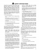
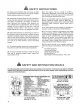
A SAFETY INSTRUCTIONS The WORKMAN® 4300-D was designed and tested to offer safe service when operated and maintained properly. Although hazard control and accident prevention partially are dependent upon the design and configuration of the machine, these factors are also dependent upon the awareness, concern, and proper training of the personnel involved in the operation, maintenance and storage of the machine. Improper use or maintenance of the machine can result in injury or death.
A SAFETY INSTRUCTIONS 18, Operator and passenger should remain seated whenever the vehicle is in motion. Operator should keep both hands on steering wheel, whenever possible and passenger should use hand holds provided. Keep arms and legs within the vehicle body at all mes. Never carry passengers in box or on attachments. Remember your passenger may not be expecting you to brake or turn and may not be dearly. 16. Never overload your vehicle.
24, Make sure all hydraulic line connectors are tight, and all hydraulic hoses and lines are in good condition before applying pressure to the system, 25. Keep body and hands away from pin hole leaks or nozzles that eject hydraulic fluid under high pressure. Use paper or cardboard, not hands, to search for leaks. Hydraulic fluid escaping under pressure can have sufficient force to penetrate skin and do serious damage.
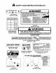
A SAFETY AND INSTRUCTION DECALS WARNING watchmaker: || RO (SWATTING ) : FLUID e, PARKING BRAKE MAXIMUM TONGUE || USE DETHRONE It WEIGHT 200 LBS. AUTOMATIC MAXIMUM TRANSMISSION 875020 TRAILER WEIGHT; FLUID OR ON CONSOLE 1500 LBS. EQUIVALENT (Part No. 87 -6020) ON AXLE TUBE TIP OVER CAN (Part No. 87-6060) o OPERATED. SPEED RANGE g INJURY OR DEATH O 5 COULD RESULT 8 e ROLL-OVER ENCASE OF 9 T Rover n m PROTECTIVE ® STRUCTURE ON CONSOLE TO MAINTAIN (Part No.
SPECIFICATIONS Type: 4 wheel step through, out front operator style, two person vehicle. Certified to meet ANSI Specifications Engine: Mitsubishi three cylinder, liquid cooled, counterbalanced, diesel engine. Rated at 23 hp, governed to a maximum speed of 3650 rpm by a mechanical governor. 58 cu. in. (852 co) displacement. Forced lubrication by gear pump. 12 volt electric starter. 8pin—on oil filter. Air Cleaner: Heavy duly, 2-stage, remote mounted air cleaner.
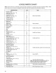
LOOSE PARTS CHART Note: Use this chart as a checklist to assure all parts necessary for assembly have been received. Without these parts, total set-up cannot be completed. Somme parts may have already been assembled at factory. DESCRIPTION Qv USE Fenders—Rear 2 Cap screw 1" g. 4 Flat washer 344" LD, 4 Lockout 4 Cap screw 1" 1g. 12 Mount rear fenders Flat washer 281" 1.D. 12 Lockout 12 Truss head Screw 6 Lockout 6 ‘Wheel Nut 10 Wheel—Front 2 Wheel Nut 10 Mount wheels.
SET-UP INSTRUCTIONS INSTALL REAR FENDERS (Fig. 1-2) 1. Loosen the lockouts and cap screws securing tail light plates to right and left frame brackets. 2. Pivot tall light plates rearward and tighten cap screws and lockouts, Figure 1 1. Alt light plate 2. Frame bracket 3. ‘fail light mounting bracket 3. Secure rear of sate tail light plate to rear of frame brackets with a x 1” Ig. cap screw, .344" LD, flat washer and nut, as shown in figure 1. 4.
SET-UP INSTRUCTIONS Figure 4 1. Steering Sheet 4. Washer 2. Jam Nut 5. Foam Seal 3. Cap INSTALL FRONT FENDERS (Fig. 5) 1. Mount a fender to each side of skirt with (7) 10-24 Phillips screws, flat washers and lockouts. Figure 5 1. Fender INSTALL SEAT FRAME (Fig. 6) 1. Mount a seat frame bracket to each end of seat frame with (2) x 3/4” carriage boils and flange lockouts. 2. Position seat frame on vehicle, aligning mounting hales in frame with holes in vehicle, 3.
SET-UP INSTRUCTIONS 3. Side manual tube into (2} R—clamps. Figure 8 1. Cushion seat back 2. Seat back bracket 3. Seat back 4. Manual tube 5. R-clamp 4. Mort cushion with seat back brackets and manual tube R-clamps to left seat back with {4) x 5/8” Ig, carriage bolts and flange lockouts. 5. Slide bed support onto storage stud (Fig. 9). Shown with seat back removed A \ Figure @ 1. Bed support 2. Storage stud INSTALL TOPS (Fig. 10) 1.
SET-UP INSTRUCTIONS Figure 11 Battery cover Knob Battery base PN 3. Remove filler caps from battery and slowly fill each cell until electrolyte is just above the plates. 4. Replace filler caps and connect a Tito 4 amp battery charger to the battery posts. Charge the battery aggravate of 316 4 amperes for 410 8 hours. 5. When battery is charged, disconnect charger from electrical outset and battery posts. 6. Remove filler caps. Slowly add electrolyte to each cell until level is up to fill ring.
BEFORE OPERATING A\ caution Before servicing or making adjustments to the machine, stop engine, set parking brake and remove key from the switch. Any load material must be removed from bed or other attachment before working under raised bed. Always place the safety support on extended lift cylinder to hold box up. CHECK CRANKCASE OIL (Fig. 13~14) The engine is shipped with approximately 3.
BEFORE OPERATING 3. Fill tank to about one inch below top of tank, (bottom of filed neck) with diesel fuel. DO NOT OVERFILL. Then install cap. 4, Wipe up any fuel that may have spieled to prevents fire hazard. A, penance Because diesel fuel is flammable, caution must be used when storing or handling it. Do not fill fuel tank while engine is running, hot, or when mariachi is in an enclosed area. Vapors may build up and be ignited by a spark or flame source many feet away.
BEFORE OPERATING Figure 18 1. Front differential 2. Spellcheck pig 3, Drain plug 3. Remove checklist plug and check level of oil. Ol should be up to hole. if oil is low, add 10W30 oil. 4. checklist plug. CHECK BRAKE FLUID (Fig. 19) The brake fluid reservoir is shipped from the factory fetid with “DOT 37 brake fluid. Check level before engine is first started and every 8 hours or daily, thereafter. 1. Park machine on a level surface, 2. Fluid level should be up to FULL line on reservoir. 3.
CONTROLS Accelerator Pedal (Fig. 20) ~ The accelerator pedal gives the operator the ability to vary engine and ground speed of the vehicle, when the transmission is in gear. Depressing the pedal increases engine. RPM and ground speed. Releasing pedal will decrease engine APM and ground speed of the machine. Figure 20 1. Accelerator pedal 2. Clutch pedal 3. Brake pedal Clutch Pedal (Fig. 20) —~The clutch pedal must be fully depressed to disengage clutch when starting engine or sniffing transmission gears.
CONTROLS Parking Brake {Fig. 21} —~Whenever the engine is shut off, the parking brake must be engaged to prevent accidental movement of the vehicle. To engage the parking brake, pull back on lever. To disengage, push lever forward. Make sure parking brake is released before moving vehicle. If vehicle is parked on a steep grade, make sure parking brake is applied. Also, shift the transmission into 1st gear on a uphill grade or reverse on a down hill grade. Place chocks at the down hilt side of wheels.
CONTROLS Glow Plug Switch and Indicator (Fig. 22) — Use to preheat engine cylinders prior to cold engine starting procedures -— cylinders are preheated automatically during warm engine start operation. For cold starting, push switch lever upward and hold while watching indicator. Indicator will glow orange when the glow plugs are activated. Length of time necessary to preheat cylinders should be determined by atmospheric temperature; refer to Starting /Stopping Engine, Ignition Switch (Fig.
OPERATING INSTRUCTIONS CHECKS Safe operation begins before taking the vehicle out for day's work. You should sack these stems each time: 1. Check tire pressure Noe: These tires are different than car tires, they require Less pressure to minimize turf compaction and damage. 2. Check all fluid levels and add the appropriate amount of Toto specified fluids, if any are found to be fow. 3. Check brake pedal operation. 4. Check to see that the lights and horn are working. 5.
OPERATING INSTRUCTIONS B ! Figure 25 . Fuel injection pump bleeder 5. Turn key in ignition switch to the ON position. Electric fuel pump will begin operation, thereby forcing air out around air bleed screw on dual injection pump. Leave key in ON position unfit solid stream of fuel flows out around the screw. Tighten screw and turn key to OFF. Note: Normally, engine should start afire above bleeding procedures are followed.
OPERATING INSTRUCTIONS 3. engine cranks or starts, there is a malfunction in the interlock system that must be repaired before operating vehicle. Refer to Attachment Operator's Manual for procedure on checking attachment interlock system. OPERATING CHARACTERISTICS The vehicle is designed with safety in mind. It has four wheels for added stability.
OPERATING INSTRUCTIONS BRAKING IN AGES OF [tis good practice to slow down before you get near an TIP OVER obstacle. This gives you extra time to stop or tum away. Hitting an obstacle can damage the vehicle and its contents. More important, it can injure you and your passenger. Gross vehicle weight has a major impact on your ability to stop and for tum. Heavier loads and heavier attachments make a vehicle harder to stop or tum. The heavier the load, the longer it takes to stop.
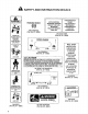
OPERATING INSTRUCTIONS TIP OVER CAN OCCUR IF TRUCK IS IMPROPERLY OPERATED. INJURY OR DEATH COULD RESULT WARNING Tipping or rolling the vehicle ona half will cause serious personal injury. e If engine stalls or you lose headway on a chili, never attempt to turn vehicle around. ¢ Always back straight down a hill in reverse gear. # Never back down in neutral or with the clutch depressed, using only the brakes. © Never drive across a steep hill, always drive straight up or down.
OPERATING INSTRUCTIONS The height and weight of the load has a significant influence on tip overs. The higher a load is stacked, the more likely the vehicle is to tip over. You may find that 2000 pounds stacks too high for safe operation. Reducing the total weight is one way to reduce the risk of a tip over. Distributing the load as low as possible is another way to reduce the risk of a tip over.
OPERATING INSTRUCTIONS TOWING VEHICLE In case of emergency, the vehicle can be towed for a short distance. However, Toto does not recommend this as a standard procedure. A WARNING Towing at excessive speeds could cause vehicle to loge steering control. Never tow vehicle faster than 5 MPH, Towing the vehicle is a two person job. Affix towline to holes in front frame member. Move sifter to Neutral and release parking brake. If machine must be moved a considerable distance, transport it on a tuck or trailer.
QUICK REFERENCE CHART st 1 WORKMAN 4300-D QUICK REFERENCE AID CHECK/SERVICE 10. FUEL PUMP 1. ENGINE OIL LEVEL 11. BATTERY 2. ENGINE OIL DRAIN 12. TIRE PRESSURE MAXIMUM 20 PSI R s 3, TRANSCENDENTALIST FRONT, 18 PSI REAR (24" TIRE) Ol LEVEL (DIP STICK) 13, FUSES (LIGHTS 10 AMP, IGNITION BELTS (GOVERNOR, WATER AP, DASH ACCESSORIES 7.5 AMP) @ 2) PUMP, HYDRAULIC PUMP) 14. HYDRAULIC STRAINER 1 12 5. COOLANT LEVEL FILL. 15, HYDRAULIC OIL FILTER = 6. FUEL (DIESEL FUEL ONLY) 16.
LUBRICATION Figure 31 Figure 29 Figure 30 IMPORTANT Heavy Duty Operation if vehicle Is subjected to conditions listed below, maintenance should be performed twice as frequently.
MAINTENANCE A caution Only qualified and authorized personnel shall be permitted to maintain, repair, adjust or inspect the vehicle. Avoid fire hazards and have fire protection equipment present in the work area.. Do not use an open flame to check level or leakage of fuel, battery electrolyte or coolant. Bono use open pans of fuel or flammable cleaning fluids for cleaning parts. Many of the subjects covered in this maintenance section require raising and lowering the bed.
MAINTENANCE 4. When jacking up front of vehicle, always place a 2x4 block {or similar material) between jack and vehicle: frame. Figure 35 1. Front jacking point Figure 36 1. Rear jacking points GENERAL AIR CLEANER MAINTENANCE PRACTICES (Fig. 37) Inspect air cleaner and hoses periodically to maintain: maximum engine protection and o ensure maximum service life, 1. Check air cleaner body for dents and other damage which could possibly cause an air leak. Replace a damaged air cleaner body. 2.
MAINTENANCE Compressed Alr Method IMPORTANT. Do not remove plastic Tin assembly because back-blowing with: compressed air removes dust firm beneath fins, A, Blow compressed air from inside o the outside of dry filter element. Do not exceed 100 psi to prevent drainage to the element, (Wear eve protection} B. Keep ait hose nozzle at jest one inch from pleated paper, and move nozzle up and down while rotating the filter element.
MAINTENANCE 3. Clean area around filter canister mounting surface. Figure 41 1. Drain plug 2. Filter canister 4. Remove filter canister and clean mounting surface. 5. Lubricate gasket on filter canister with clean engine oil. 6. Install filter canister by hand until gasket contacts mourning surface, then rotate an additional 1/2 turn. Fuel Pump Filter Remove and replace the filter after every 400 hours operation. 1.
MAINTENANCE 3. Slowly depress accelerator pedal to full FAST position. 4, Turnkey in key switch to START position and watch fuel flow around connector. Turk key to OFF position when solid flow is observed. 5. Tighten pipe connector securely. &. Repeat steps and 3 nozzles. REMOVING DEBRIS FROM ENGINE COOLING SYSTEM (Fig. 44) Remove debris from engine area and radiator daily, clean more frequently in dirty conditions. 1. Remove radiator cover. 2. Turpentine off. Clean engine area thoroughly of alf debris. 3.
MAINTENANCE 2. To adjust belt tension: ADJUSTING ACCELERATOR PEDAL (Fig. engine throttle lever does not contact high idle stop B. Using a bar, rotate alternator until proper belt when accelerator pedal is fully depressed, an tension is attained, then tighten mounting bolts. adjustment o the accelerator cable is required. 1. Positiveness on level surface, stop engine and engage the parking brake. A. Loosen alternator mounting bolts, Note: Engine must not be running and return spring must be attached. 2.
MAINTENANCE CHANGING TRANS AXLE / HYDRAULIC FLUID (pig. 49) Change Trans axle hydraulic fluid, filter and clean strainer every 600 hours. 1. Position the vehicle on a level surface, stop engine, engage the parking brake and remove key from ignition switch. 2. Remove drain plug from side of reservoir and let hydraulic fluid flow into drain pan. Reinstall and tighten plug when hydraulic fluid stops draining. 3. Fill reservoir with approximately 7.5 gt. of Dethrone | ATF. Refer to Checking Hydraulic Fluid. 4.
MAINTENANCE 2. Remove drain plug {Fig. 49) from side of reservoir and let hydraulic fluid flow into drain pan. 3. Remove hydraulically _and fitting. connected to strainer on side of reservoir. 4. Remove strainer and clean by back flushing with a clean greaser. Allow to air dry before reinstalling. Figure 52 1. Hydraulic strainer 5. Reinstall strainer. 6. Reinstall hydraulic line and fitting to strainer. 7. Reinstall and tighten drain plug. 8. Fill reservoir with approximately 7.5 gt.
MAINTENANCE ADJUSTING Check adjustment every 200 hours. 1. Loosen set screw securing knob to parking brake fever. 2. Rotate knob until a force of 3545 Ibs. is required ‘o actuate lever. 3§, Tighten set screw after adjustment has been attained. @ \ Figure 57 4. Parking brake lover 2 Knob 3. Setscrew ADJUSTING SHIFT Check adjustment every 200 hours. 1. Wove shift lever to Neural position. 2. Remove clevis pins securing shift cables to trans axle shift arms. 3.
MAINTENANCE 3. While pulling back on spring, adjust jam news to abstain .035" +.025" gap between spring hook and O.D. of hole in transient lever. 4. Tighten jam nuts after adjustment has been attained and recheck, EMERGENCY BOX RAISING {without starting engine) The box can be raised in an emergency by cranking starter and holding lift lever. Run starter for 15 seconds then Walt 60 seconds before engaging starter again.
SUMP STARTING PROCEDURE WARNING 'Jump can To avoid personal injury or damage lo electrical components in vehicle, ch serve the following warnings: o M Never jump sitar with a voltage sources greater than 15 vols D.C. This will damage the electrical system, o Never template to jump start a discharged battery that is frozen. R could rupture or explode diving jump starting. o Observe all battery warnings while jump starting your vehicle. © Be sure your vehicle is not touching the jump stat vehicle.
SERVICE INTERVAL CHART Date Hour Meter Reading Service Interval Daily 10 50 100 150 200 250 Check interlock System Daily Check Engine Oil Level Daily Check Trans axle Oil Level Deity Check Radiator & Coolant Daily {More often when conditions are dirty) Check Brake Fluid Level Daily Check Tire Pressure Daily Replace Hydraulic Ol Filter {initial) 10 Check Belt Tensions (initial) 10 Check Cable Adjustments (initial} 10 Tighten Wheel Nuts (initial) 2 &10 Service Air Cleaner (Dust Cup & Baffle) 50 {More often wh
IDENTIFICATION AND ORDERING MODEL AND SERIAL NUMBERS The WORKMAN® 4300-D has two identification numbers: a model number and a serial number. These numbers are stamped into a plate located on the right frame member under dash. In any correspondence concerning the unit, supply the model and serial numbers ta ensure correct information and replacement parts are obtained. 44 Note: Do not order by reference number if a parts catalog is being used; use the part number.
component manufacturer: Commercial Products The Tore Promise A One Oar Limited Warranty The Toto Company promises 1o repair your model 07215 Workman 4300-D vehicle if defective in materials or workmanship. The following Rime periods from the date of purchase apply (special warranty terms, on certain compo nerds, may be offered through The Toto Company by the The cast of parts, labor and transportation are included. recommended: 1.