3 3 3 3 " ,48,' 22/(' ,(6(/ 2 $6685( 0$;,080 6$)(7< 237,080 3(5)250$1&( $1' 72 *$,1 .
The TORO WORKMAN was developed to provide an efficient, versatile, trouble free and economical work vehicle. The latest concepts of engineering, design and safety have been incorporated into this machine, along with the highest quality parts and workmanship. Excellent service will be derived if proper operation and maintenance practices are followed. # $, ' (!! #$"#0 1 / #$ % ('%1 ' $, '(- ,$"' *.$)) (+ & '.! -.+ !(+ ., (' ).
The TORO WORKMANR meets the requirements of ANSI B56.8a-1994. Supervisors, operators and service persons should be familiar with the following standards and publications: (The material may be obtained from the address shown). D Flammable and Combustible Liquids Code: ANSI/NFPA 30 D National Fire Protection Association: ANSI/NFPA #505; Powered Industrial Trucks ADDRESS: National Fire Prevention Association Barrymarch Park Quincy, Massachusetts 02269 U.S.A D ANSI/ASME B56.
. . . . . . . . . . . . . . . . . . . . 5-7 . . . . . . 8-10 . . . . . . . . . . . . . . . . . . . . . . . . . . . 11 . . . . . . . . . . . . . . . . . . . . . . 12 . . . . . . . . . . . . . . . . 13-15 Install Rear Fenders . . . . . . . . . . . . . . . . . . . . . . . 13 Install Wheels . . . . . . . . . . . . . . . . . . . . . . . . . . . . 13 Install Steering Wheel . . . . . . . . . . . . .
! "& !" # " ! ".+ % <'8 *+8/-4+* '4* 9+89+* 95 5,,+7 8',+ 8+7;/)+ <.+4 56+7'9+* '4* 3'/49'/4+* 6756+72> 29.5:-. .'?'7* )549752 '4* '))/*+49 67+;+49/54 6'79/'22> '7+ *+6+4*+49 :654 9.+ *+8/-4 '4* )54,/-:7'9/54 5, 9.+ 3')./4+ 9.+8+ ,')9578 '7+ '285 *+6+4*+49 :654 9.+ '<'7+4+88 )54)+74 '4* 6756+7 97'/4/4- 5, 9.+ 6+78544+2 /4;52;+* /4 9.+ 56+7'9/54 3'/49+4'4)+ '4* 8957'-+ 5, 9.+ 3')./4+ 36756+7 :8+ 57 3'/49+4'4)+ 5, 9.+ 3')./4+ )'4 7+8:29 /4 /40:7> 57 *+'9. ".
When starting the engine: Sit on operator's seat and engage parking brake. Disengage any attachments and return hand throttle lever to OFF position (if so equipped). Move shift lever to NEUTRAL and depress clutch pedal. Keep foot off accelerator pedal. Turn ignition key to ON, hold glow plug switch ON. (Maximum 30 seconds) Turn ignition key to START. Using the machine demands attention.
Before disconnecting or performing any work on the hydraulic system, all pressure in system must be relieved by stopping engine, cycling dump valve from raise to lower and/or lowering box and attachments. Place the remote hydraulics lever in the float position. If box must be in raised position, secure with safety support. To make sure entire machine is in good condition, keep all nuts, bolts and screws properly tightened.
# $( #$"% $ # $0- .5225<14/ 8).-9= )4, 14897:+9154 ,-+)28 )7- 1489)22-, 54 90- 3)+014- . )4= *-+53- ,)3)/-, 57 122-/1*2- 7-62)+- 90-3 -+)2 6)79 4:3*-78 )7- 2189-, *-25< )4, 14 90- 6)798 +)9)25/ 7,-7 7-62)+-3-498 .
# $) #$"% $ # % " # ($ $ %# !*12 0 # "$ !*12 0 ' " $ # " # #!" # ! " $ "# % " # ## ) !" %" #!" " !*12 0 $ ) "# #%!! "$ !*12 0 $ #$ ! $$ ") & " !*12 0 # !*12 0 " $ " $ " !*12 0 $ " " !*12 0 #%!! "$ !*12 0 % " " $ # # !*12 0 4-,,/ +1.
# $) #$"% $ # # *-. , $ " $ ( % $ % ' $ # ( % $" " ' $ # $" # ## % %# (" + %$ $ $" # ## % " !% & $ ( $% *-. , # *-. , # *-. , " # *-. , " $ " $ " *-. , " # *-. , # *-. , # "$ *-.
1) 4 wheel step through, out front operator style, two person vehicle. Certified Specifications B56.8a-1994. to meet ANSI ' "' Mitsubishi three cylinder, liquid cooled, counterbalanced, diesel engine. Rated at 23 hp, governed to a maximum speed of 3650 rpm by a mechanical governor. 58 cu. in. (952 cc) displacement. Forced lubrication by gear pump. 12 volt electric starter. Spin-on oil filter. "* % ' * Heavy duty, 2Ćstage, remote mounted air cleaner.
Use this chart as a checklist to assure all parts necessary for assembly have been received. Without these parts, total setĆup cannot be completed. Some parts may have already been assembled at factory. Fenders-Rear Capscrew 5/16-18 x 1" lg. Flatwasher .344" I.D. Locknut 5/16-18 Capscrew 1/4-20 x 1" lg. Flatwasher .281" I.D.
)' Loosen the locknuts and capscrews securing tail light plates to right and left frame brackets. Pivot tail light plates rearward and tighten capscrews and locknuts. On left side, loosely secure tail light mounting bracket, rear of fender and tail light plate together with (2) capscrews, washers and nuts, previously removed. On right side, secure rear of fender to tail light plate with (2) 1/4-20 x 1" lg. capscrews, .281" I.D.
! ! +)52' 4''2+/) "*'' #. 54 #1 "#3*'2 0#. '#- +) +)52' Mount a fender to each side of skirt with (7) 10-24 Phillips screws, flat washers and locknuts. '#4 (2#.' '#4 (2#.' $2#%,'4 ! ! ! ! +) Mount (2) seat back brackets to each seat back cushion with (4) 1/4-20 x 3/4" lg. capscrews and 1/4" flat washers.
! " ! " ! Slide manual tube into (2) R-clamps. .,96* 97-.43 7*&8 '&(0 *&8 '&(0 '6&(0*8 *&8 '&(0 Secure each side of ROPS to mounting brackets with (2) 1/2-13 x 3" lg. capscrews and locknuts. ! &39&1 89'* (1&25 Mount cushion with seat back brackets and manual tube R-clamps to left seat back with (4) 5/16-18 x 5/8" lg. carriage bolts and flange locknuts. Slide bed support onto storage stud (Fig. 9). .,96* 4938.
! " # !" # " ! -+85) %77)5; '39)5 23& %77)5; &%6) Remove filler caps from battery and slowly fill each cell until electrolyte is just above the plates. Replace filler caps and connect a 3 to 4 amp battery charger to the battery posts. Charge the battery at a rate of 3 to 4 amperes for 4 to 8 hours.
! "! '(14' 5'48+%+0) 14 /#-+0) #&,756/'065 61 6*' /#%*+0' 5612 '0)+0' 5'6 2#4-+0) $4#-' #0& 4'/18' -'; (41/ 6*' 59+6%* 0; .1#& /#6'4+#. /756 $' 4'/18'& (41/ $'& 14 16*'4 #66#%*< /'06 $'(14' 914-+0) 70&'4 4#+5'& $'& .9#;5 2.#%' 6*' 5#('6; 5722146 10 ':6'0&'& .+(6 %;.+0< &'4 61 *1.& $1: 72 ! ! *'%- .'8'. 1( 1+. '8'4; 12'4#6+0) *1745 14 &#+.; *#0)' 1+. #0& (+.6'4 +0+6+#..; #(6'4 6*' (+456 *1745 1( 12'4#6+10 6*'4'#(6'4 %*#0)' 1+. #0& (+.
! Fill tank to about one inch below top of tank, (bottom of filler neck) with diesel fuel. ! # Then install cap. Wipe up any fuel that may have spilled to prevent a fire hazard. +)'97+ */+7+1 ,9+1 /7 ,1'22'(1+ )'98/43 2978 (+ 97+* ;.+3 7846/3- 46 .'3*1/3- /8 4 348 ,/11 ,9+1 8'30 ;./1+ +3-/3+ /7 6933/3- .48 46 ;.+3 2')./3+ /7 /3 '3 +3)147+* '6+' #'5467 2'= (9/1* 95 '3* (+ /-3/8+* (= ' 75'60 46 ,1'2+ 7496)+ 2'3= ,++8 ';'= ! ;./1+ ,/11/3- 8.
# ! # % Higher pressures should be used for heavier payloads at higher speeds. Do not exceed the maximum pressure. Use the following charts to determine correct tire pressures for tire size and payload of vehicle. ! #% % When replacing vehicle tires, only use replacements approved for the Workman. Use of tires not approved may cause turf damage or accelerated drive train damage. % #"& ' &%$ ' # )14=:- <7 5)16<)16 8:78-: <7:9=- +7=4, :-;=4< 16 .)14=:- 7: 47;; 7.
! The brake fluid reservoir is shipped from the factory filled with DOT 3" brake fluid. Check level before engine is first started and every 8 hours or daily, thereafter. Park machine on a level surface. Fluid level should be up to FULL line on reservoir. If fluid level is low, clean area around cap, remove reservoir cap and fill to proper level. .
CONTROLS Accelerator Pedal (Fig. 20) - The accelerator pedal gives the operator the ability to vary engine and ground speed of the vehicle, when the transmission is in gear. Depressing the pedal increases engine RPM and ground speed. Releasing pedal will decrease engine RPM and ground speed of the machine. 1 2 3 Figure 20 1. Accelerator pedal 2. Clutch pedal 3. Brake pedal Clutch Pedal (Fig.
!0*)-' 0!*% (Fig. 21) -Whenever the engine is shut off, the parking brake must be engaged to prevent accidental movement of the vehicle. To engage the parking brake, pull back on lever. To disengage, push lever forward. Make sure parking brake is released before moving vehicle. If vehicle is parked on a steep grade, make sure parking brake is applied. Also, shift the transmission into 1st gear on a uphill grade or reverse on a down hill grade. Place chocks at the down hill side of wheels.
&!+!'& .!+ (Fig. 22) -The ignition switch, used to start and stop the engine, has three positions: OFF, ON / Preheat and START. Rotate key clockwise Ċ START position Ċ to engage starter motor. Release key when engine starts. The key will move automatically to the ON position. To shut engine off, rotate key counterclockwise to OFF position. ) & ! +') (Fig. 22) - Illuminates when battery is being discharged.
! ! " ! ! ! Safe operation begins before taking the vehicle out for a day's work. You should check these items each time: Check tire pressure. 15( These tires are different than car tires, they require less pressure to minimize turf compaction and damage. Check all fluid levels and add the appropriate amount of Toro specified fluids, if any are found to be low. Check brake pedal operation. Check to see that the lights and horn are working.
! To stop engine, rotate ignition key to OFF and engage parking brake. Remove key from switch to prevent accidental starting. # " -+85) 8)0 -2.)'7-32 4814 &0))()5 Turn key in ignition switch to the ON position. Electric fuel pump will begin operation, thereby forcing air out around air bleed screw on fuel injection pump. Leave key in ON position until solid stream of fuel flows out around the screw. Tighten screw and turn key to OFF.
) 0 ,$!2 &/. # $(. ,&) % -1$. # )* , .$)( Sit on operator's seat and engage parking brake. Move shift lever to NEUTRAL position. Without depressing clutch pedal, rotate key clockwise to start position. If engine cranks or starts, there is a malfunction in the interlock system that must be repaired before operating vehicle. ! , .) .. #' (. * , .), - (/ & !), *,) /, )( # %$(" .. #' (. $(. ,&) % -2-.
Wet, sandy and slippery surfaces make turning more difficult and risky. The faster you are going, the worse this situation becomes so, slow down before turning. During a sharp turn at higher speeds, the inside rear wheel may lift off of the ground. This is not a flaw in the design, it happens with most four wheel vehicles including passenger cars. If this happens, you are turning too sharply for the speed at which you are traveling.
If you stall or begin to lose headway while climbing a steep hill, quickly apply the brakes, shift to neutral, restart the engine and shift to reverse. At idle speed, engine and transaxle drag will aid the brakes in controlling the vehicle on the hill and help you back down the hill more safely. Reduce the weight of the load if it is a steep hill or if the load has high center of gravity. Remember, loads can shift. Secure them. (, The Workman has excellent hill climbing ability.
The height and weight of the load has a significant influence on tip overs. The higher a load is stacked, the more likely the vehicle is to tip over. You may find that 2000 pounds stacks too high for safe operation. Reducing the total weight is one way to reduce the risk of a tip over. Distributing the load as low as possible is another way to reduce the risk of a tip over.
In case of emergency, the vehicle can be towed for a short distance. However, Toro does not recommend this as a standard procedure. /6*.( "3 &7$&22*5& 20&&%2 $/4,% $"42& 5&)*$,& 3/ ,/2& 23&&1*.( $/.31/, &5&1 3/6 5&)*$,& '"23&1 3)". When equipped with a tow hitch bolted onto rear axle tube, your Workman can tow trailers or attachments with a Gross Trailer Weight (GTW) up to 1500 lbs.
&/" 1& ' +1,(". +/&0&+* This is the position which will lift the rear hitch attachment or apply pressure to quick coupler "B". This also allows return oil from Quick coupler "A" to flow back into the valve and then out to the power steering circuit. This is a momentary position and when the lever is released it spring returns to the center off position. Use double acting cylinders only.
Difficulty in connecting or disconnecting quick couplers. Pressure not relieved (Quick coupler under pressure). Engine running. Remote hydraulic valve not placed in float. Power steering hard. Remote valve not in neutral or float position. Remote hydraulic valve linkage out of adjustment. Hydraulic oil level low. Hydraulic oil hot. Hydraulic leaks. Fittings loose. Fitting missing o-ring. Attachment does not function.
Daily Maintenance: (duplicate this page for routine use) Check proper section of Operator's Manual for fluid specifications Daily Maintenance Check For Week Of _________________ Maintenance C Check Item b MON TUES WED THURS FRI SAT SUN n Safety Interlock Operation n Service & Park Brake Operation n Fuel Level n Accelerator Operation n Clutch & Shifter Operation n Engine Oil Level n Transaxle Oil Level n Cooling System Fluid Level1 n Brake Fluid Level n Air C
! " '(13' 4'37+%+0) 13 /#-+0) #&,645/'054 51 5*' /#%*+0' 4512 '0)+0' 4'5 2#3-+0) $3#-' #0& 3'/17' -': (31/ +)0+5+10 48+5%* 0: .1#& /#; 5'3+#. /645 $' 3'/17'& (31/ $'& 13 15*'3 #5; 5#%*/'05 $'(13' 813-+0) 60&'3 3#+4'& $'& .; 8#:4 2.#%' 5*' 4#('5: 4622135 10 '95'0&'& .+(5 %:.+0&'3 51 *1.& $19 62 ! +) The vehicle has grease fittings that must be lubricated regularly with No. 2 General Purpose Lithium Base Grease.
-0 ,+0 ' ) + &% - # * *, ! + +& &% + &%* # *+ #&. $ %+ % % * &,# ' ) &)$ +. * ) (, %+#0 D * )+ &' ) + &% D &# # $ + &' ) + &% #&. _ D ) # ) &) + . # +&. % D ) (, %+ &' ) + &% &% ,*+0 )& * D ) (, %+ &' ) + &% ,% ) $ / $,$ - # )&** . + D &%*+), + &% .&)" D + ) /+ % &' ) + &% % $, * % . + ) &) * $ # ) )+0 &% + &%* - 0&,) ) " * %*' + % # % % ) - /# !& %+* ) * * *&&% * '&** # * .
! Push bed support onto cylinder rod, making sure support end tabs rest on end of cylinder barrel and on cylinder rod end (Fig. 36). "! 31= 6:&1.+.*) &3) &:9-47.>*) 5*78433*1 8-&11 '* 5*72.99*) 94 2&.39&.3 7*5&.7 &)/:89 47 .3? 85*(9 9-* ;*-.(1* ;4.) +.7* -&>&7)8 &3) -&;* +.7* 5749*(9.43 *6:.52*39 57*8*39 .3 9-* <470 &7*& 4 349 :8* &3 45*3 +1&2* 94 (-*(0 1*;*1 47 1*&0&,* 4+ +:*1 '&99*7= *1*(9741=9* 47 (441&39 4 349 :8* 45*3 5&38 4+ +:*1 47 +1&22&'1* (1*&3.3, +1:.)8 +47 (1*&3.
(&30% %"0 )"#*(-& /.(-21 (& Inspect air cleaner and hoses periodically to maintain maximum engine protection and to ensure maximum service life. Check air cleaner body for damage which could possibly cause an air leak. Replace a damaged air cleaner body. Clean the air cleaner filter every50 hours and change every 200 hours (more frequently in extreme dusty or dirty conditions).
Clean area around filter canister mounting surface. $#-*! '#$'! $% $%,!* Remove oil filter. Apply a light coat of clean oil to the new filter seal before screwing it on. Screw filter on until gasket contacts mounting plate, then tighten 1/2 to 2/3 of a turn. DO NOT OVER-TIGHTEN. Add oil to crankcase, refer to Check Engine Oil.
Slowly depress accelerator pedal to full FAST position. Turn key in key switch to START position and watch fuel flow around connector. Turn key to OFF position when solid flow is observed. Tighten pipe connector securely. Repeat steps 1Ć4 on No. 2 and 3 nozzles. " # ,* Remove debris from engine area and radiator daily, clean more frequently in dirty conditions. Remove radiator cover. ,*74( Turn engine off.
Remove radiator and reserve tank caps. )(2/' #&)#1-/ %#. '0'/3' 1#,* %#. Open coolant drain cock at bottom of radiator and allow coolant to flow into drain pan. When coolant stops, close drain cock. Remove coolant drain plug from engine and allow coolant to flow into drain pan. When coolant stops, install drain plug. Slowly fill radiator with a 50/50 mixture of water and permanent ethylene glycol anti-freeze. Install radiator cap.
26( Engine must not be running and return spring must be attached. Fill reservoir with approximately 7.5 qt. of Dexron IIl ATF. Refer to Checking Hydraulic Fluid. Adjust ball joint on accelerator cable to allow .100"-.250" clearance between accelerator pedal and top of diamond tread floor plate, when a 25 lb. force is applied to center of pedal. Tighten locknut. Start engine and operate to fill hydraulic system. Recheck oil level and replenish, if required.
! ! ! 4216 #,))0 4-8) 2()05 109 -+ Change front differential oil every 800 hours. Position vehicle on a level surface, stop engine, engage parking brake and remove key from ignition switch. Clean area around drain plug on side of differential. Place drain pan under drain plug. -+74) 9(4%70-' 564%-1)4 " ! -+ Check adjustment every 200 hours. Loosen jam nut on link rod ball joint.
# $"# $# ,* Check adjustment every 200 hours. Loosen jam nuts securing clutch cable to bracket on bell housing. 26) Ball joint may be removed and rotated If additional adjustment is required. Disconnect return spring from clutch lever. Adjust jam nuts and/or ball joint until bottom rear edge of clutch pedal is 3.75" + .12" from top of floor plate diamond pattern, when an 4 lb. force is applied to pedal.
! While pulling back on spring, adjust jam nuts to obtain .035" ± .025" gap between spring hook and O.D. of hole in transaxle lever. Tighten jam nuts after adjustment has been attained and recheck. % $ :.7-387 67&57.2, *2,.2* The box can be raised in an emergency by cranking starter and holding lift lever. Run starter for 15 seconds then wait 60 seconds before engaging starter again.
MAINTENANCE JUMP STARTING PROCEDURE WARNING Jump starting can be dangerous. To avoid personal injury or damage to electrical comĆ ponents in vehicle, observe the following warnings: D 1 D Figure 63 D 1. Tie rod 3. Rotate tie rod outward. to move front of tire inward or 4. Tighten tie rod jam nuts when adjustment is correct. INSPECT CONSTANT VELOCITY BOOT Four Wheel Drive Models Only After every 200 operating hours, inspect constant velocity boot for cracks, holes or a loose clamp.
If the machine will be stored for more than 30 days, remove the battery and charge it fully. Either store it on the shelf or on the machine. Leave the cables disconnected if stored on the machine. Store the battery in a cool atmosphere to avoid quick deterioration of the charge in the battery. To prevent battery from freezing, make sure it is fully charged. The specific gravity of a fully charged battery is 1.250.
! Check Battery Fluid Level Check Battery Cable Connections Check Dust Cup/Baffle ! ! Every 50hrs Every 100hrs Every 200hrs Every 400hrs Every 800hrs Lubricate All Grease Fittings Inspect Condition and Wear of Tires Check Front Differential Oil Level (4WD) } Change Engine Oil and Filter Inspect Cooling System Hoses { Check Cable Adjustments { Check Alternator and Fan Belts Service Air Filter Check Fro
10
10 ' !#% ( $ & % " " (
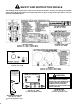
BLACK YEL/BK FUEL PUMP A B C PULL WHITE BLACK HOLD RED GROUND BLACK BLACK DIODE + RED 87A 85 86 DIODE BLACK HI-LO LOCKOUT SWITCH 2-3 LOCKOUT SWITCH 30 87 PINK R/W PINK ALTERNATOR R S TACH P L B STARTER G B R/W 10 GA FUSIBLE LINK R/BK - BLACK PINK BLUE R/BK BU/WHT OFF = CLOSED PTO (OPT) CLUTCH SWITCH TEMP SENDER GRN/BK YELLOW VIOLET BN/WHT OIL PRESSURE (OPEN WHEN RUNNING) 85 30 GRAY RED RED WHT/BK BROWN TAIL/BRAKE LIGHT FUEL SENDER GRAY YELLOW RED 8
BLACK BLACK YEL/BK FUEL PUMP C B A BROWN BLACK HOLD RED BROWN BLACK DIODE 86-7470 + RED S 86 85 87A BLACK HI-LO LOCKOUT SWITCH 2-3 LOCKOUT SWITCH R/W 30 BLACK PINK BLUE 86-7470 DIODE 87 PINK ALTERNATOR R TACH L P B STARTER G B FUSIBLE LINK 67-7120 PINK 86 BU/WHT OFF = CLOSED HYD. SWITCH TAIL/BRAKE LIGHT IGNITION BROWN RED RED TEMP SENDER GRN/BK YELLOW VIOLET BN/WHT OIL PRESSURE (OPEN WHEN RUNNING) 7.5 AMP FUSE 218-574 10\ AMP\ FUSE 218-578 PTO (OPT) 85 87A
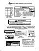
The WORKMAN has two identification numbers: a model number and a serial number. These numbers are stamped into a plate located on the right frame member under dash. In any correspondence concerning the unit, supply the model and serial numbers to ensure correct information and replacement parts are obtained. Do not order by reference number if a parts catalog is being used; use the part number.
(% .1. .,,%1#)!+ 1.$4#32 6. %!1 ),)3%$ !11!-38 (% .1. .,/!-8 6!11!-32 8.41 .1 -%6%1 .1. .,,%1#)!+ 1.$4#3 9 1.$4#3 /41#(!2%$ !&3%1 !-4!18 3. "% &1%% &1., $%&%#32 )- ,!3%1)!+2 .1 6.1*,!-2()/ &.1 3(% /%1).$ .& 3),% +)23%$ "%+.6 (%1% ! 6!11!-3!"+% #.-$)3).- %7)232 .1. 6)++ 1%/!)1 3(% 1.$4#3 !3 -. #.23 3. 8.4 )-#+4$)-' $)!'-.2)2 +!".1 /!132 !-$ 31!-2/.13!3).- ()2 6!11!-38 "%')-2 .- 3(% $!3% 3(% 1.$4#3 )2 $%+)5%1%$ 3. 3(% .1)')-!+ 1%3!)+ /41#(!2%1 !11!-38 41!3).- 6.