
Operator's Manual


6
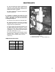
BUMPER ASSEMBLY 99-0805:
1. The two (92-2700) Hitch Arm Brackets are to
be installed on the Rear Channels of the
Workman® unit. The short leg of Bracket
(channel) should be at the top. See FIG. 1.
Using four (two for each bracket) 3/8-16 x 1
Lg. Flange Lock Hex. Hd. Cap Screws, mount
Brackets to the Workman
®
units channels.
Tighten screws securely with four 3/8 Flange
Lock Nuts.
2. Slide (99-0468) Bumper Assembly between
Rear Channels of the Workman
®
unit. Mount
(99-0468) Bumper Assembly to the (92-2700)
Hitch Arm Brackets installed in Step 1. Using
two (one for each side) 1/2-13 x 1-1/2 Lg. Hex.
Hd. Cap Screws, insert screws through the larger
holes in Bumper and larger holes in Hitch Arm
Bracket. Place a 1/2 Flange Lock Nut on each
screw. Do not tighten screws completely at this
time. Insert two (one on each bracket) 3/8-16 x
1-1/2 Lg. Hex Hd. Cap Screws through the
smaller holes in Bumper and smaller holes in
Hitch Arm Bracket. Place a 3/8 Flange Lock
Nut on each screw. Do not tighten screws
completely at this time. See FIG. 1.
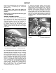
3. Using two (92-2752) U-Bolts, (one for each
side) wrap the U-Bolts around the Transaxle
Support Tube on the Workman
®
unit. Insert the
threaded ends of the U-Bolts through Welded
Brackets on the Bumper Assembly. Using four
(two for each U-Bolt) 3/8 Flange Lock Nuts,
equally tighten each side of the U-Bolts securely.
See FIG. 2. Securely tighten the four screws and
nuts on the Hitch Arm Brackets previously
installed in Step 2. The Bumper Assembly is now
complete.
SET-UP
NOTE: Right, Left, Front, and Rear are
referenced while seated in the operators
position.
NOTE: Refer to Torque Specifications on page
5 for all Fasteners.
Refer to the Illustrated Parts List for the details of
parts used in assembling the Industrial
Workman
®
kit.
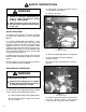
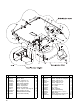
FIG. 1
1. Hitch Arm Bracket (Short leg) 2. Bumper Assembly
1641
1
2
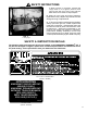
FIG. 2
1. U-Bolt 2. Transaxle Support Tube
1642
1
2