
Operator's Manual


7
4. Lift (99-0465) Skid Plate up to the (99-0466)
Adjustment Plate. Mount the two Plates together
using two 3/8-16 x 1 Lg. Flange Lock Hex.
Hd. Cap Screws and 3/8 Flange Lock Nuts. The
Assembly is now complete.
SKID PLATE ASSEMBLY 99-0806:
(Requires 99-0805 Bumper Assembly)
1. Mount (99-0465) Skid Plate to Bumper
Assembly, using two 3/8-16 x 1 Lg. Flange
Lock Hex. Hd. Cap Screws. Slide the two screws
through the welded Bumper Bracket and through
the two Skid Plate mounting holes. See
Illustration on page 11, (Model No. 99-0805 and
99-0806) Items 1 and 3. Loosely place a 3/8
Flange Lock Nut on each screw.
2. The (99-0466) Adjustment Plate can be located
in two different places on the Skid Plate. The
mounting depends on which type of unit you are
installing the Adjustment Plate on. The Gasoline
units Adjustment Plate is located all the way to
the right on the Skid Plate. The Diesel units
Adjustment Plate is located all the way to the left.
See Illustration on page 11, (Model No. 99-0806)
Item 2.
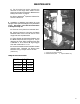
3. Making sure (99-0466) Adjustment Plate has
the welded nuts up toward the unit, slide
Adjustment Plate over the Workman
®
units Oil
Pan Guard, (this Guard has two holes for
mounting the Adjustment Plate) secure it into
place using two 3/8-16 x 5/8 Lg. Hex. Hd. Cap
Screws. IMPORTANT: Make sure these
screws are not too long and do not rupture
the oil pan when tightening. See FIG. 3.
Tighten all screws and nuts securely.
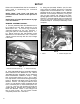
TANK GUARD ASSEMBLY:
1. Position Tank Guard over the Fuel Tank. Using
three 3/8-16 x 1 Lg. Flange Lock Hex. Hd.
Cap Screws to mount the Tank Guard Assembly,
place the screws into the three existing insert
holes in Workman
®
unit. These existing inserts
are located behind the Fuel Tank on the Rear
Channel (Frame) of the Workman
®
unit. See FIG.
4. Tighten screws securely.
2. Install (99-0463) Guard Brace Strap with the
3/8-16 x 1 Lg. Flange Lock Hex. Hd. Cap Screw
and 3/8 Flange Lock Nut. Attach the Guard
Brace Strap on top of bottom panel of Tank
Guard. Slide the screw through Strap and
through Tank Guard. See Illustration on page
10, Items 5 and 6. Tighten nut onto screw, leaving
nut finger tight. The other end of the Strap should
be attached to the bottom Channel of the
Workman
®
unit. Using a 3/8-16 x 1 Lg. screw,
slide screw through the Workman
®
unit Channel
and through the Strap, then place nut on screw.
Securely tighten both screws and nuts holding
the Strap. The Assembly is now complete.
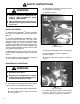
SET-UP
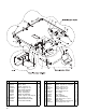
FIG. 3
1. Adjustment Plate 3. Oil Pan Guard
2. Skid Plate 4. Welded Nut
1643
2
4
3
1
NOTE: Refer to Torque Specifications on page
5 for all Fasteners.
NOTE: Refer to Torque Specifications on page
5 for all Fasteners.
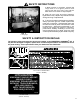
FIG. 4
1. Tank Guard Assy 3. Fuel Tank
2. Existing Inserts Location
1644
1
2
3