Form No. 3437-913 Rev A Workman® MDX-D Utility Vehicle Model No. 07236—Serial No. 401380001 and Up Model No. 07236TC—Serial No. 401380001 and Up Register at www.Toro.com.
Whenever you need service, genuine Toro parts, or additional information, contact an Authorized Service Distributor or Toro Customer Service and have the model and serial numbers of your product ready. Figure 1 identifies the location of the model and serial numbers on the product. Write the numbers in the space provided. This product complies with all relevant European directives; for details, please see the separate product specific Declaration of Conformity (DOC) sheet.
Contents Replacing the Fuses ......................................... 36 Maintaining the Headlights ............................... 36 Drive System Maintenance .................................. 38 Maintaining the Tires ........................................ 38 Inspecting the Steering and Suspension Components ................................................. 38 Adjusting the Front Wheel Alignment ................ 39 Checking the Transaxle-Fluid Level .................. 40 Changing the Transaxle Fluid .
Safety • Do not put your hands or feet near moving This machine has been designed in accordance with the requirements of SAE J2258 (Nov 2016). • Do not operate the machine without all guards General Safety • Keep bystanders and children out of the operating This product is capable of causing personal injury. Always follow all safety instructions to avoid serious personal injury. • Stop and shut off the machine and remove the key components of the machine.
decal115-2412 115-2412 decal106-6755 1. Warning—read the Operator's Manual; no storage. 106-6755 1. Engine coolant under pressure. 3. Warning—do not touch the hot surface. 2. Explosion hazard—read the Operator's Manual. 4. Warning—read the Operator's Manual. decal115-7739 115-7739 1. Falling, crushing hazard—do not carry passengers. decal119-9727 119-9727 1. Horn 7. Power point 2. Hour meter 8. Warning—read the Operator's Manual. 3. Headlights 9.
decal120-4837 120-4837 1. Read the Operator's Manual for information on fuses. 2. Alarm/power point (10 A) 5. Machine fuse (15 A) 6. Lift (15 A) 3. Engine (10 A) 7. Rear lift (15 A) 4. Headlights (10 A) 8. Horn (30 A) decal121-9775 121-9775 1. Warning—read the Operator’s Manual and receive training before operating the machine. 4.
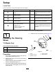
Setup Loose Parts Use the chart below to verify that all parts have been shipped. Procedure 1 2 3 4 5 Description Use Qty. Steering wheel Cover Washer (1/2 inch) 1 1 1 Install the steering wheel (TC models only). No parts required – Connect the battery (TC models only). No parts required – Check the fluid levels and tire pressure. No parts required – Burnish (break-in) the brakes.
2 Connecting the Battery TC Models Only No Parts Required g228187 Procedure Figure 5 1. Insulator boot (positive battery cable) WARNING 2. Negative battery cable (black) Incorrectly routing the battery cable could damage the machine and cables, causing sparks. Sparks can cause the battery gasses to explode, resulting in personal injury. 4. • Always disconnect the negative battery cable (black) before disconnecting the positive battery cable (red). 5.
4 Burnishing the Brakes No Parts Required Procedure To ensure optimum performance of the brake system, burnish (break-in) the brakes before use. 1. Bring the machine up to full speed, apply the brakes to rapidly stop the machine without locking up the tires. 2. Repeat this procedure 10 times, waiting 1 minute between stops, to avoid overheating the brakes. Important: This procedure is most effective if the machine is loaded with 227 kg (500 lb).
Product Overview g033215 Figure 6 1. Hood latch 3. Cargo bed 5. Gear-shift selector 2. Parking-brake lever 4. Towing tongue 6. Fuel-tank cap 10 7.
Parking-Brake Lever Controls The parking-brake lever is located between the seats (Figure 6 and Figure 7). Whenever you shut off the engine, engage the parking brake to prevent the machine from accidentally moving. To engage the parking brake, pull up the parking-brake lever. To disengage the parking brake, push the lever down. Control Panel Gear-Shift Selector The gear-shift selector is located between the seats and below the parking-brake lever.
Light Switch Key Switch Use the light switch (Figure 8) to illuminate the headlights. Push the light switch up to turn on the headlights. Push the light switch down to turn off the lights. Use the key switch (Figure 8), to start and shut off the engine. The key switch has 3 positions: OFF, ON, and START . Rotate the key clockwise to the ON position to activate the glow plugs. When the glow-plug-indicator light turns off, rotate the key clockwise to the START position.
Fuel Gauge The fuel gauge (Figure 9) is located on the fuel tank next to the filler cap, at the left side of the machine. The gauge displays the amount of fuel in the tank. g008398 Figure 9 1. Empty 4. Fuel gauge 2. Full 5. Fuel-tank cap 3. Needle Passenger Handholds The passenger handholds are located on the right side of the dash panel and at the outside of each seat (Figure 10). g009193 Figure 10 1. Handhold—hip restraint 2.
Specifications Note: Specifications and design are subject to change without notice. Base weight Dry 590 kg (1,300 lb) Rated capacity (on level ground) 749 kg (1,650 lb) total, including 90.7 kg (200 lb) operator and 90.
Performing Daily Maintenance Operation Note: Determine the left and right sides of the machine from the normal operating position. Service Interval: Before each use or daily Before Operation Before starting the machine each day, perform the Each Use/Daily procedures listed in Maintenance (page 23).
Adding Fuel Breaking in a New Machine The engine runs on clean, fresh diesel fuel with a minimum cetane rating of 40. Purchase fuel in quantities that you can use within 30 days to ensure fuel freshness. Service Interval: After the first 100 hours—Perform the guidelines for breaking in a new machine. Perform the following guidelines to provide proper performance for the machine. Use summer-grade diesel fuel (No. 2-D) at temperatures above -7°C (20°F) and winter grade diesel fuel (No. 1-D or No.
During Operation During Operation Safety • General Safety • The owner/operator can prevent and is responsible • • • • • • • • • • • • • for accidents that may cause personal injury or property damage. Passengers should sit in the designated seating positions only. Do not carry passengers in the cargo bed. Keep bystanders and children out of the operating area. Wear appropriate clothing, including eye protection; long pants; substantial, slip-resistant footwear; and hearing protection.
in weight distribution may cause the machine to overturn. in rough terrain, or on a slope, which could result in a rollover. Contact an Authorized Service Dealer for more information. Slopes are a major factor related to loss-of-control and tip-over accidents, which can result in severe injury or death. Operating the Cargo Bed • Survey the site to determine which slopes are Raising the Cargo Bed safe for operating the machine and establish your own procedures and rules for operating on those slopes.
Opening the Tailgate 1. Ensure that the cargo bed is down and latched. 2. Lift up the finger pulls at the back panel of the tailgate (Figure 15). g014860 Figure 13 1. Lever 2. Prop rod 2. 3. Detent slot Pull the prop rod into the detent slot to secure the bed (Figure 14). g024490 Figure 15 1. Tailgate flange (cargo bed) 3. Lift up (finger pull) 2. Lock flange (tailgate) 4. Rotate rearward and down 3.
Stopping the Machine Important: When stopping the machine on an incline, use the service brakes to stop the machine and engage the parking brake to hold the machine in place. Using the accelerator to stall the machine on the hill can damage the machine. 1. Remove your foot from the accelerator pedal. 2. Slowly press the brake pedal to apply the service brakes until the machine comes to a complete stop. g024491 Figure 16 1. Rotate the tailgate to approximately the 45° position. 3.
After Operation Important: Loss of steering control or the machine may tip over if you position the load behind the rear axle and the traction on the front tires is reduced. After Operation Safety • Use extra caution when transporting oversized loads in the cargo bed, particularly when you cannot center the weight of the oversize load to the cargo bed.
2. Affix a tow line to the tongue at the front of the machine frame (Figure 17). 3. Move the transmission to the NEUTRAL position and disengage the parking brake. Towing a Trailer The machine is capable of pulling trailers. A tow hitch is available for the machine. Contact your Authorized Service Dealer for details. g033043 Figure 17 When hauling cargo or towing a trailer, do not overload your machine or trailer.
Maintenance • If possible, do not perform maintenance while the Maintenance Safety • If you must run the machine to perform a machine is running. Keep away from moving parts. maintenance adjustment, keep your hands, feet, clothing, and any parts of the body away from any moving parts. Keep bystanders away from the machine. • Do not allow untrained personnel to service the • • • • • • • machine. Before you leave the operating position, do the following: – Park the machine on a level surface.
Maintenance Service Interval Maintenance Procedure Every 100 hours • • • • • • • • • • Every 150 hours • Change the engine oil (twice as often in special operating conditions; refer to . • Change the engine-oil filter. Change the oil twice as often during special operating conditions. Every 200 hours • • • • Every 300 hours • Grease the front wheel bearings. Every 400 hours • Inspect the fuel lines and connections. • Visually inspect the brakes for worn brake shoes.
Daily Maintenance Checklist Duplicate this page for routine use. Maintenance Check Item For the week of: Monday Tuesday Wednesday Thursday Friday Saturday Sunday Check the brake and parking brake operation. Check the gear shift/neutral operation. Check the fuel level. Check the engine-oil level. Check the transaxle-fluid level. Inspect the air filter. Inspect the engine-cooling fins. Check for unusual engine noises. Check for unusual operating noises. Check the tire pressure. Check for fluid leaks.
Pre-Maintenance Procedures Many of the subjects covered in this maintenance section require raising and lowering the bed. To prevent serious injury or death, take the following precautions. Preparing the Machine for Maintenance 1. Park the machine on a level surface. 2. Engage the parking brake. 3. Shut off the engine and remove the key. 4. Empty and raise the cargo bed; refer to Operating the Cargo Bed (page 18). g033043 Figure 19 1.
Accessing the Hood Lubrication Raising the Hood Greasing the Machine 1. Lift up the handle of the rubber latches on each side of the hood (Figure 21). Service Interval: Every 100 hours/Yearly (whichever comes first)—Grease the bearings and bushings. Grease the machine more frequently when using it for heavy-duty operations. Grease Type: No. 2 lithium grease 1. Use a rag to wipe the grease fitting clean so that foreign matter cannot be forced into the bearing or bushing. 2.
Greasing the Front Wheel Bearings Service Interval: Every 300 hours Grease specification: Mobilgrease XHP™-222 Removing the Hub and Rotor 1. Lift the front of the machine and support it with jack stands. 2. Remove the 4 lug nuts that secure the wheel to the hub (Figure 24). g033047 Figure 25 1. Flange-head bolts (3/8 x 3/4 inch) 3. Caliper bracket (brake assembly) 2. Spindle 4. Remove the dust cap from the hub (Figure 26). g033046 Figure 24 1. Hub 3. Lug nut 2. Wheel 3.
Greasing the Wheel Bearings 1. Remove the outboard bearing and bearing race from the hub (Figure 28). g033049 Figure 27 1. Spindle 2. Hub and rotor assembly 7. Wipe clean the spindle with a rag. 8. Repeat steps 1 through 7 to the hub and rotor at the other side of the machine. g033050 Figure 28 1. Seal 4. Bearing cavity (hub) 2. Inboard bearing 5. Outboard-bearing race 3. Inboard-bearing race 6. Outboard bearing 2. Remove the seal, inboard bearing from the hub (Figure 28). 3.
Installing the Hub and Rotor 1. Apply a light coat of the specified grease to the spindle (Figure 29). g033054 Figure 30 1. Cotter pin 3. Dust cap 2. Nut retainer g033051 Figure 29 1. Nut retainer 4. Outer bearing 2. Spindle nut 5. Hub, rotor, inner bearing, race, and seal 6. Spindle 3. Tab washer 2. Assemble the hub and rotor onto the spindle with the rotor inboard (Figure 29). 3. Assemble the outboard bearing onto the spindle and seat the bearing to the outboard race (Figure 29). 4.
Engine Maintenance Note: Avoid knocking the filter against the air-filter housing. 6. Engine Safety • If the air-filter element is clean, install the • Shut off the engine, remove the key, and wait for filter element. all moving parts to stop before checking the oil or adding oil to the crankcase. • If the air-filter element is damaged, replace the filter element; refer to Replacing the Air Filter (page 31).
Servicing the Engine Oil Note: Change the oil more frequently when operating conditions are extremely dusty or sandy. Note: Dispose of the used engine oil and oil filter at a certified recycling center. Engine-Oil Specifications Oil Type: Detergent oil (API service CH-4, CI-4, CJ-4, or higher) Crankcase Capacity: 1.4 L (1.5 US qt) when the filter is changed Viscosity: See the table below. g016858 Figure 33 1. Fill cap 6. Remove the dipstick and wipe it clean. 7.
6. Start and run the engine to check for oil leaks. 7. Shut off the engine and check the engine-oil level. Note: If necessary, add the specified oil into the engine until the oil level is at the Full mark on the dipstick. g027838 Figure 34 1. Engine-oil filter 8. 2. Drain plug Remove the drain plug (Figure 34). Note: Allow the oil to completely drain from the engine. 9. Install the drain plug and seal (Figure 34) and torque the plug to 45 to 53 N∙m (33 to 39 ft-lb). 10.
Fuel System Maintenance Electrical System Maintenance Inspecting Fuel Lines and Connections Electrical System Safety • Disconnect the battery before repairing the machine. Disconnect the negative terminal first and the positive last. Connect the positive terminal first and the negative last.
Installing the Battery WARNING 1. Battery terminals or metal tools could short against metal machine components, causing sparks. Sparks can cause the battery gasses to explode, resulting in personal injury. • When removing or installing the battery, do not allow the battery terminals to touch any metal parts of the machine. • Do not allow metal tools to short between the battery terminals and metal parts of the machine. 1. Align the battery to the battery tray of the machine (Figure 36).
Replacing the Fuses CAUTION The bulbs become extremely hot when in operation. Handling a hot bulb can cause severe burns and personal injury. There are 7 fuses in the electrical system. They are located beneath the hood (Figure 37). Alarm/Power Point 10 A Engine 10 A Headlights 10 A Machine fuse 15 A Lift 15 A Rear lift 15 A Horn 30 A Always allow enough time to for the bulbs to cool before replacing them. Use care whenever handling the bulbs. Specification: See your Parts Catalog. 1.
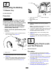
Adjusting the Headlights Replacing the Headlight 1. Disconnect the battery; refer to Disconnecting the Battery (page 34). 2. Open the hood; refer to Raising the Hood (page 27). 3. Use the following procedure to adjust the headlight beam position whenever a headlight assembly is replaced or removed. Disconnect the electrical connector for the harness from the connector of the lamp assembly (Figure 39). g036873 Figure 39 1. Speed clip 4. Headlight 2. Opening in the bumper 5. Lamp assembly 3.
Drive System Maintenance Maintaining the Tires Service Interval: Every 100 hours—Check the condition of the tires and rims. Every 100 hours—Torque the wheel-lug nuts. 1. Inspect the tires and rims for signs of wear and damage. Note: Operating accidents, such as hitting curbs, can damage a tire or rim and also disrupt wheel alignment, so inspect tire condition after an accident. g313199 2. Figure 40 Torque the wheel lug nuts to 108 to 122 N∙m (80 to 90 ft-lb). 1.
Adjusting the Front Wheel Alignment Adjusting the Front Wheel Toe-in Important: Before adjusting toe-in, ensure that the camber adjustment is as close to neutral as possible; refer to Adjusting the Camber (page 39). Service Interval: Every 100 hours/Yearly (whichever comes first)—Check the front wheel camber and toe-in. 1. Preparing to Adjust Camber or Toe-in 1. 2. 3. Check the tire pressure to ensure that the front tires are inflated to 82 kPa (12 psi).
Checking the Transaxle-Fluid Level Service Interval: Every 100 hours Fluid Type: SAE 10W30 (API service SJ or higher) 1. 2. Park the machine on a level surface, engage the parking brake, shut off the engine, and remove the key. g002109 Figure 46 Remove the bolt from the level-indicating hole (Figure 45). 1. Drain plug Note: The transaxle fluid level should be at the bottom of the level indicator hole. 3. Align a drain pan with a capacity of 2 L (2.1 qt) or more under the drain plug. 4.
10. Check the fluid level and add more fluid if the level is below the threads of the fill-plug hole (Figure 46). 5. Checking and Adjusting Neutral Pull up on each shift cable an ensure that there is a 0.76 to 1.52 mm (0.03 to 0.06 inch) between the nut/washer and the neutral bracket (Figure 49). Note: If there is a not a gap, adjust the nuts to achieve the specified gap.
Maintaining the Primary Drive Clutch Cooling System Maintenance Service Interval: Every 200 hours—Clean the primary drive clutch (more often in dusty or dirty conditions). Cooling System Safety Note: Operating the machine with a dirty clutch can • Swallowing engine coolant can cause poisoning; keep out of reach from children and pets. increase wear to internal components. 1. Park the machine on a level surface, engage the parking brake, shut off the engine, and remove the key. 2.
Changing the Radiator Coolant Servicing the Radiator Service Interval: Every 1,000 hours/Every 2 years (whichever comes first) Checking the Radiator-Coolant Level CAUTION Service Interval: Before each use or daily If the engine has been running, the pressurized, hot coolant can escape and cause burns. Note: Use a 50/50 mix of ethylene glycol and water for coolant. 1. Park the machine on a level surface, shut off the engine, engage the parking brake, and remove the key. 2.
Brake Maintenance Note: The level should be above the Minimum line. Inspecting the Brakes Service Interval: Every 100 hours Important: Brakes are a critical safety component of the machine. Closely inspect them at the recommended service interval to ensure optimum performance and safety. • Inspect the brake lining for wear or damage. If the lining (brake pad) thickness is less than 1.6 mm (1/16 inch), replace the brake lining.
2. Loosen the set screw securing the brake-adjustment knob to the parking-brake lever (Figure 54). A. Loosen the forward jam nut (Figure 55) for the threaded adjuster of the parking-brake cable 1 turn. 3. Rotate the brake-adjustment knob until you reach a force of 133 to 156 N∙m (30 to 35 ft-lb) to engage the parking-brake lever (Figure 54). B. Tighten the rear jam nut (Figure 55). C.
Belt Maintenance Servicing the Drive Belt Rotate and route the belt over the secondary clutch (Figure 56). 7. Lower the cargo bed. Checking the Belt-Pull Bumper Checking the Drive Belt Service Interval: After the first 8 hours Note: Check the belt-pull bumper only when troubleshooting vibration, performing a rebuild, or experiencing an engine-mount failure. Every 200 hours 1. 6. Park the machine on a level surface, engage the parking brake, shut off the engine, and remove the key. 2.
Chassis Maintenance Cleaning Adjusting the Cargo-Bed Latches Washing the Machine Service Interval: Before each use or daily—Wash the machine. If the cargo-bed latch is out of adjustment, the cargo bed vibrates up and down as you drive the machine. You can adjust the latch posts to make the latches hold the cargo bed snugly to the chassis. 1. Wash the machine as needed using water alone or with a mild detergent. You may use a rag when washing the machine.
Storage damaged at temperatures below 0°C (32°F). A fully charged battery maintains its charge for about 50 days at temperatures lower than 4°C (40°F). If the temperatures will be above 4°C (40°F), check the water level in the battery and charge it every 30 days. Storage Safety • Shut off the machine, remove the key, and wait for all movement to stop before you leave the operator’s position. Allow the machine to cool before adjusting, servicing, cleaning, or storing it. 13.
Notes:
EEA/UK Privacy Notice Toro’s Use of Your Personal Information The Toro Company (“Toro”) respects your privacy. When you purchase our products, we may collect certain personal information about you, either directly from you or through your local Toro company or dealer.
California Proposition 65 Warning Information What is this warning? You may see a product for sale that has a warning label like the following: WARNING: Cancer and Reproductive Harm—www.p65Warnings.ca.gov. What is Prop 65? Prop 65 applies to any company operating in California, selling products in California, or manufacturing products that may be sold in or brought into California.
The Toro Warranty Two-Year or 1,500 Hours Limited Warranty Conditions and Products Covered Parts The Toro Company and its affiliate, Toro Warranty Company, pursuant to an agreement between them, jointly warrant your Toro Commercial product (“Product”) to be free from defects in materials or workmanship for 2 years or 1,500 operational hours*, whichever occurs first. This warranty is applicable to all products with the exception of Aerators (refer to separate warranty statements for these products).