
Installation Instructions


2
Installing the Rear Lift Kit
1. Position the machine on a level surface. Set the parking
brake, turn the ignition off, and remove the key.
If you leave the key in the ignition switch, someone
could accidently start the engine and seriously
injure you or other bystanders.
Remove the key from the ignition switch before
you do any maintenance.
Caution
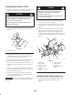
2. Remove a short battery cable linking any two batteries
in the battery bank to remove power from the system
(Fig. 1).
m–7650
1
Figure 1
1. Short battery cable
3. Remove the 4 bolts and 4 flange nuts securing the
existing hitch plate to the vehicle. Discard the hitch
plate, retain all the fasteners for later use.
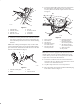
4. Align the holes in the rear lift frame with the holes in
the rear and bottom of the vehicle frame (Fig. 2).
5. Secure each end of the rear lift frame to the rear of the
vehicle frame with 3 bolts (3/8 x 1 inch) as shown in
Figure 2.
6. Secure each end of the rear lift frame to the underside
of the vehicle frame with 2 bolts (3/8 x 1 inch) and 2
flange nuts (3/8 inch) (Fig. 2).
7. Secure the center of the rear lift frame with 4 bolts
(3/8 x 1 inch) and 4 flange nuts (3/8 inch) previously
removed as shown in Figure 2.
Important If a trailer ball is attached to the hitch plate,
the hitch plate must be removed during operation of the
rear lift.
Damage to the actuator may occur if the hitch
plate with a trailer ball is attached during
operation of the rear lift.
• Only use a hitch plate with a trailer ball when
the actuator is removed.
Caution
8. Install the hitch plate to the rear lift frame using the
large clevis pin and hair pin (Fig. 2).
9. Secure the actuator to the lift with the small clevis pin
and hairpin (Fig. 2). Position the actuator as shown in
Figure 2.
10. Connect the rear lift harness to the actuator. Plug the
other end of the rear lift harness into the connector
labeled linear actuator on the main vehicle harness,
located near the input hole of the controller cover. The
controller cover is located in the right, rear of the frame
(Fig. 2).
1
2
5
7
8
3
3
4
6
10
9
3
m–7658
Figure 2
1. Vehicle frame
2. Rear lift frame
3. Bolt, 3/8 x 1 inch
4. Flange nut, 3/8 inch
5. Actuator
6. Clevis pin, small and
hairpin
7. Rear lift harness
8. Vehicle harness
9. Hitch plate
10. Clevis pin, large and
hairpin
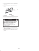
Installing the Wiring Harness
1. Install the solenoid on existing plate using two bolts
(#10 x 3/4 inch) and two nuts (#10) as shown in
Figure 3.