
Installation Instructions


3
2
1
6
7
8
4
5
3
m–7653
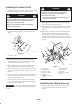
Figure 3
1. Solenoid plate
2. Solenoid, existing
3. Solenoid, new
4. Bolt, #10 x 3/4 inch
5. Nut, #10
6. Accessory harness
7. Large posts
8. Small posts
2. Attach the accessory harness to the solenoid. Connect a
large ring to each large post. Connect a small ring wire
to to each small post. Secure the wires with the existing
fasteners
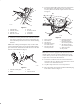
Note: If the existing solenoid plate is full, use the U–bolt
and 2 locknuts (3/8 inch) to secure the solenoid mounting
plate to the frame. Install the solenoid and connect the wire
harness as described above (Fig. 4).
3
1
4
2
m–7657
Figure 4
1. Solenoid mounting plate
2. Frame
3. U-bolt
4. Locknut, 3/8 inch
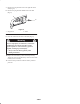
3. Locate the optional 48v output connector as labeled on
the main harness and remove the cap. Connect the
accessory harness to the 48v output connector as shown
in Figure 5.
4
3
5
8
6
7
2
9
10
1
m–7658
Figure 5
1. Dash, underside
2. Main harness
3. Wire harness
4. 48v output connector,
from main harness
5. 48v connector, from
accessory harness
6. Rear lift kit connector,
from main harness
7. Rear lift kit connector,
from accessory harness
8. 48v output connector,
from accessory harness
9. Switch connector
10. Plug in dash
Note: If the vehicle is equipped with a box lift kit, locate
the 48v output connector on the box lift kit harness and
remove the cap. Connect the accessory harness to the 48v
output connect on the box lift kit harness.
4. Locate the rear lift kit connector on the main harness
and remove the cap. Attach accessory harness to rear kit
connector. wire from main harness.
5. Cap 48v output connector on accessory harness.
6. Place the switch connector into position behind the plug
in the dash as shown in Figure 5.