
Installation Instructions
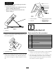
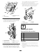
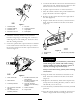
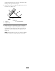
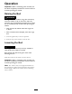


Figure4
1.Bed
3.Flangeheadscrew,5/16
x3/4inch
2.Upperliftbracket
3.Looselymounttheliftcylindersupporttotheright
endoftherearaxlewith2U-boltsand4angenuts
(3/8inch)whilealigningthemountingholeswith
theholesinthebatterytray(Figure5).
Figure5
1.Liftcylindersupport
4.U-bolt
2.Rightendoftheaxle5.Carriagebolt,3/8x3/4
inch
3.Rearframebatterytray6.Flangenut,3/8inch
4.Securetheliftcylindersupporttotherearframe
with2carriagebolts(3/8x3/4inch)and2ange
nuts(3/8inch).Tightenthe4angenutsonthe
U-boltsequallytomakesurethebracketisalignedto
theaxle.Tightenthetwonutssecuringtherearof
thebrackettotherearframe(
Figure5).
5.Mountthebottomendoftheliftactuatortothelift
cylindersupportwithaclevispinandcotterpin.
Positionthecomponentsasshownin
Figure6.
Figure6
1.Actuator
3.Clevispin
2.Liftcylindersupport4.Cotterpin
3
InstallingtheSwitch
Partsneededforthisprocedure:
1
Solenoid
2
Bolt(#10x3/4inch)
2
Nut(#10)
1Accessoryharness
1
Switch
1
Clevispin,large
1
Cotterpin
Procedure
1.Removethehoodtoaccessthemainharnessand
solenoidplate.
2.Installthesolenoidontheexistingplateusingtwo
bolts(#10x3/4inch)andtwonuts(#10)asshown
in
Figure7.
3