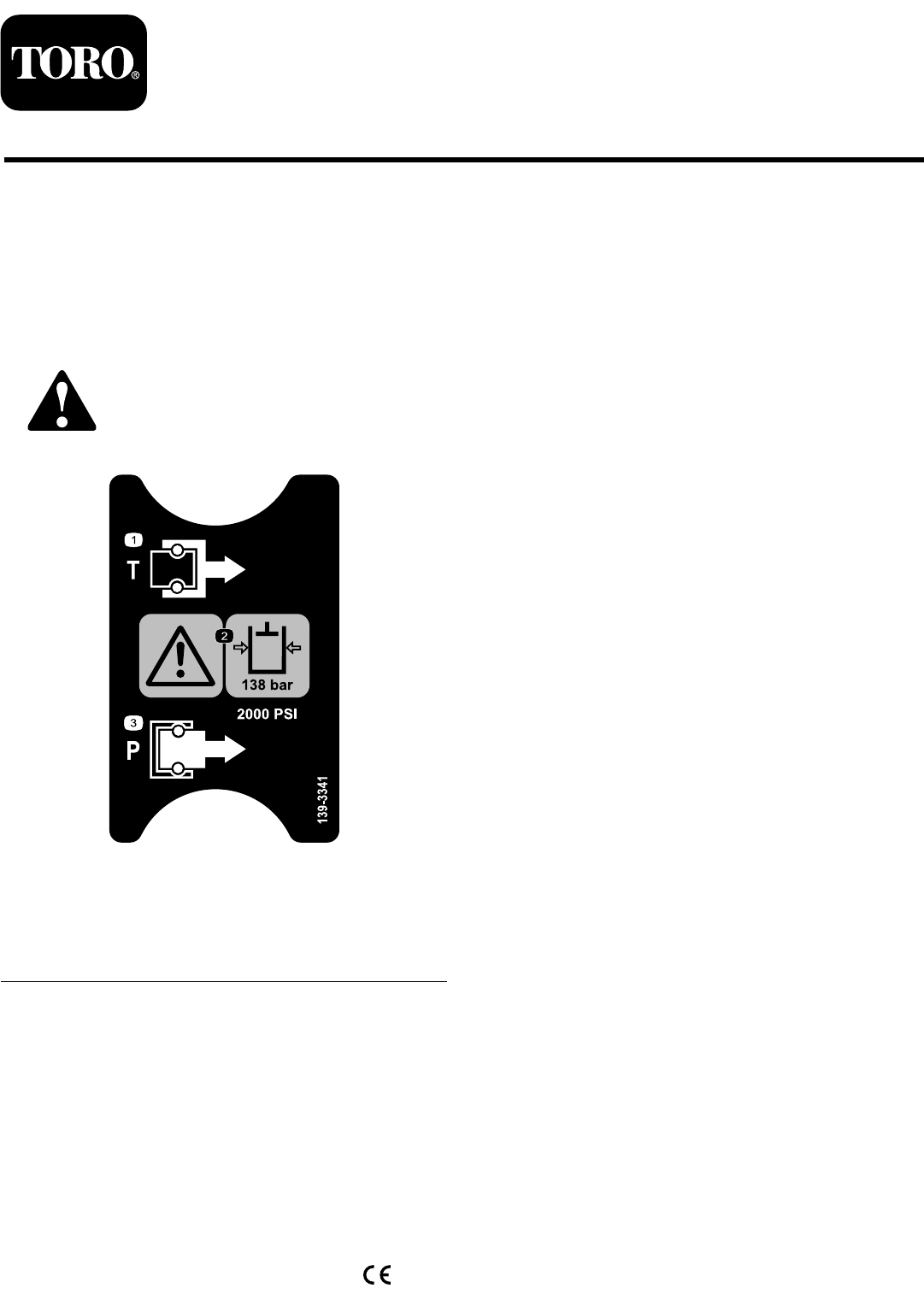
Form No. 3408-313 Rev D High-Flow Hydraulic Kit Workman® HDX or HDX-D Series Utility Vehicle Model No. 07316 Installation Instructions Safety Safety and Instructional Decals Safety decals and instructions are easily visible to the operator and are located near any area of potential danger. Replace any decal that is damaged or missing. decal139-3341 139-3341 1. Tank 2. Warning—the hydraulic-fluid pressure is 138 bar (2,000 psi).
Installation Loose Parts Use the chart below to verify that all parts have been shipped. Procedure 1 2 3 4 5 6 7 8 9 10 11 12 Description Use Qty. No parts required – Prepare the machine. No parts required – Remove the cargo bed. No parts required – Remove the radiator screen. No parts required – Remove the hood. High-flow pump assembly 1 Install the hydraulic pump.
Procedure 13 14 15 Description Use Qty. Hose (3/4 x 7 inches) Hose (1/2 x 14-1/2 inches) Hose (1/2 x 51 inches) with fitting Hose (1/2 x 63 inches) High-pressure hose (32 inches) Large hose clamp Small hose clamp Cable tie Switch Decal Harness adapter 1 1 1 1 1 2 5 2 1 1 1 No parts required – Install the hydraulic hoses. Install the switch. Fill the hydraulic reservoir with fluid. 1 Preparing the Machine No Parts Required Procedure 1. Park the machine on a level surface. 2.
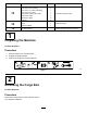
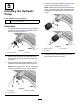
3 4 Removing the Radiator Screen Removing the Hood No Parts Required No Parts Required Procedure 1. Procedure Open the latches and remove the radiator screen from the radiator housing (Figure 2). While grasping the hood in the headlight openings, lift up the hood to release the lower mounting tabs from the frame slots (Figure 3). g010315 Figure 2 1. Radiator screen 2. Latch g010314 Figure 3 1. Hood 4 2.
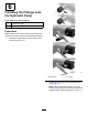
4. 5 Using the 2 long bolts, assemble the high-flow pump onto the existing pump (Figure 6). Note: Make sure that the mating surfaces are clean, and that the stub shaft is lubricated with Molybdenum Grease and is inserted into the pump. Installing the Hydraulic Pump Parts needed for this procedure: 1 High-flow pump assembly Procedure 1. Thoroughly clean the area around the hydraulic pump end cap to prevent contamination from entering the pump (Figure 4). g009929 Figure 6 1.
Installing the Fittings onto the Hydraulic Pump Parts needed for this procedure: 1 90° fitting with O-rings 1 Straight fitting with O-rings Procedure Note: Make sure that the O-rings are lubricated with hydraulic fluid and in place before installing the fittings. 1. Thread the straight fitting into the driver’s side of the pump (Figure 7). g009930 Figure 7 1. Straight fitting 2. 2. 90° fitting Thread the 90° fitting into the right side of the pump (Figure 7).
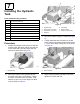
Installing the Hydraulic Tank Parts needed for this procedure: 1 Hydraulic-tank assembly 2 Cable tie g254515 Figure 9 2 Small P-clamp 2 Tank clamp 1. Hydraulic tank 5. Tank clamp 2 Screw (5/16 x 2 inches) 2. Screw (5/16 x 2 inches) 6. Small P-clamp 2 Flat washer (11/32 inch) 3. Flat washer (11/32 inch) 7. Flange nut (5/16 inch) 2 Tank hold-down 2 Flange-head screw (5/16 x 1 inch) 4 Flange nut (5/16 inch) 4. Cable tie 3. Secure the cables using the 2 cable ties (Figure 9). 4.
4. 8 Installing the Hydraulic Filter Parts needed for this procedure: 1 Hydraulic filter 1 Filter head 1 90° barbed fitting 1 Straight barbed fitting with O-ring 2 Flange-head screw (1/4 x 3/4 inch) Procedure Note: Make sure that the O-rings are lubricated with hydraulic fluid and in place before installing the fittings. 1. Mount a 90° barbed fitting to the inlet port of the filter head (Figure 11). g009935 Figure 11 1. Filter head 4. Hydraulic filter 2. 90° barbed fitting 5.
10 Installing the Valve Install the Quick-Coupler Assembly Parts needed for this procedure: 1 Valve 2 T fitting 2 Flange-head screw (1/4 x 1-7/8 inches) Parts needed for this procedure: 1 Quick-coupler assembly 2 Flange-head screw (1/4 x 3/4 inch) 2 Flange nut (1/4 inch) Procedure Procedure Note: Make sure that the O-rings are lubricated with hydraulic fluid and in place before installing the fittings. 1. Loosely install the 2 T fittings onto the valve (Figure 12). 2.
11 12 Installing the Hydraulic Lines Installing the Cooler Parts needed for this procedure: 1 Parts needed for this procedure: 2 Hard hydraulic line 2 Hard-line clamp 1 Screw (5/16 x 1-1/2 inches) Procedure Procedure 1. Cooler Loosely install a hard hydraulic line to the lower quick coupler and rear T fitting on the valve (Figure 14). 1. Insert the cooler-mounting tabs into the slots below the radiator (Figure 15). 2.
Important: Ensure that you use a cable tie to 13 secure the hoses away from the exhaust, as this damages the hoses. Installing the Hydraulic Hoses Parts needed for this procedure: 1 Hose (3/4 x 7 inches) 1 Hose (1/2 x 14-1/2 inches) 1 Hose (1/2 x 51 inches) with fitting 1 Hose (1/2 x 63 inches) 1 High-pressure hose (32 inches) 2 Large hose clamp 5 Small hose clamp 2 g009942 Figure 16 Cable tie 1. Hose (1/2 x 63 inches) 4. Hose (1/2 x 51 inches) Procedure 2.
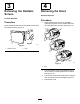
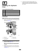
14 Installing the Switch Parts needed for this procedure: g009945 Figure 19 1 Switch 1 Decal 1 Harness adapter 1. Switch Procedure 1. Remove a plug from an unused opening in the dash panel (Figure 17). g009943 Figure 17 1. Dash-panel opening 2. 2. Plug Insert the switch into the dash-panel opening (Figure 18). g009944 Figure 18 1. Decal 2. Switch 3. Apply the decal to the dash panel next to the switch (Figure 18). 4.
15 1. Clean the area around the filler neck and the cap of the hydraulic tank (Figure 20). 2. Remove the cap from the filler neck. Filling the Hydraulic Reservoir with Fluid No Parts Required Procedure g009946 Figure 20 The hydraulic reservoir must be filled with approximately 15.1 L (4 US gallons) of high-quality hydraulic fluid. Check the level of hydraulic fluid before starting the engine, and daily, thereafter. The appropriate hydraulic fluids are listed below. 1.
Maintenance Changing the Hydraulic Fluid and Filter Change the hydraulic fluid after every 800 hours. Change the hydraulic filter: • After the first 10 hours • After every 800 hours If the hydraulic fluid becomes contaminated, contact your local Toro distributor to flush the system. Contaminated fluid may look milky or black when compared to clean fluid.
Schematics g009947 Hydraulic Schematic (Rev.